Nissan Pathfinder (2005 year). Manual - part 298
CAN SYSTEM (TYPE 2)
LAN-83
[CAN]
C
D
E
F
G
H
I
J
L
M
A
B
LAN
2005 Pathfinder
2.
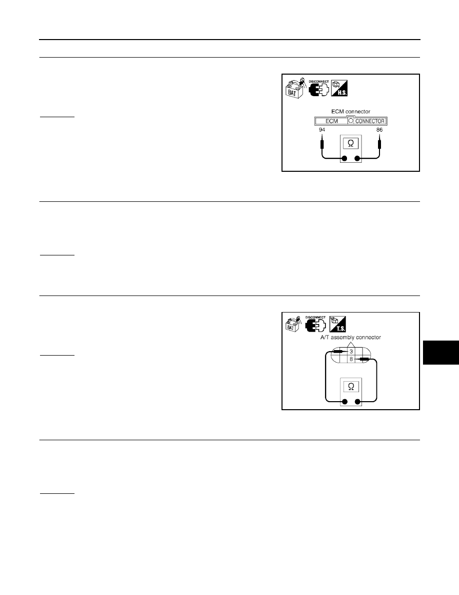
CHECK HARNESS FOR OPEN CIRCUIT
1.
Disconnect ECM connector.
2.
Check resistance between ECM harness connector E16 termi-
nals 94 (L) and 86 (P).
OK or NG
OK
>> Replace ECM.
NG
>> Repair harness between ECM and A/T assembly.
TCM Circuit Inspection
UKS003FR
1.
CHECK CONNECTOR
1.
Turn ignition switch OFF.
2.
Disconnect the battery cable from the negative terminal.
3.
Check terminals and connector of A/T assembly for damage, bend and loose connection (control module
side and harness side).
OK or NG
OK
>> GO TO 2.
NG
>> Repair terminal or connector.
2.
CHECK HARNESS FOR OPEN CIRCUIT
1.
Disconnect A/T assembly connector.
2.
Check resistance between A/T assembly harness connector F9
terminals 3 (L) and 8 (P).
OK or NG
OK
>> Replace control valve with TCM.
NG
>> Repair harness between A/T assembly and harness
connector F14.
Steering Angle Sensor Circuit Inspection
UKS003FS
1.
CHECK CONNECTOR
1.
Turn ignition switch OFF.
2.
Disconnect the battery cable from the negative terminal.
3.
Check terminals and connector of steering angle sensor for damage, bend and loose connection (sensor
side and harness side).
OK or NG
OK
>> GO TO 2.
NG
>> Repair terminal or connector.
94 (L) – 86 (P)
: Approx. 108 – 132
Ω
PKIA9592E
3 (L) – 8 (P)
: Approx. 54 – 66
Ω
SKIA6866E