Nissan Pathfinder (2005 year). Manual - part 195
DTC P1111, P1136 IVT CONTROL SOLENOID VALVE
EC-411
C
D
E
F
G
H
I
J
K
L
M
A
EC
2005 Pathfinder
DTC P1111, P1136 IVT CONTROL SOLENOID VALVE
PFP:23796
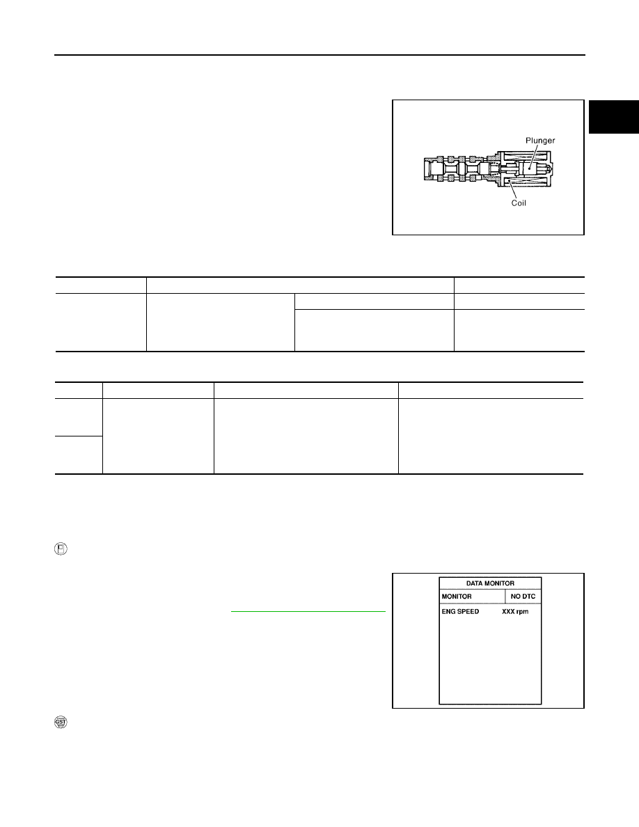
Component Description
UBS00KBT
Intake valve timing control solenoid valve is activated by ON/OFF
pulse duty (ratio) signals from the ECM.
The intake valve timing control solenoid valve changes the oil
amount and direction of flow through intake valve timing control unit
or stops oil flow.
The longer pulse width advances valve angle.
The shorter pulse width retards valve angle.
When ON and OFF pulse widths become equal, the solenoid valve
stops oil pressure flow to fix the intake valve angle at the control
position.
CONSULT-II Reference Value in Data Monitor Mode
UBS00KBU
Specification data are reference values.
On Board Diagnosis Logic
UBS00KBV
DTC Confirmation Procedure
UBS00KBW
NOTE:
If DTC Confirmation Procedure has been previously conducted, always turn ignition switch OFF and
wait at least 10 seconds before conducting the next test.
WITH CONSULT-II
1.
Turn ignition switch ON.
2.
Select “DATA MONITOR” mode with CONSULT-II.
3.
Start engine and let it idle for 5 seconds.
4.
If 1st trip DTC is detected, go to
EC-415, "Diagnostic Procedure"
.
WITH GST
Following the procedure “WITH CONSULT-II” above.
PBIB1842E
MONITOR ITEM
CONDITION
SPECIFICATION
INT/V SOL (B1)
INT/V SOL (B2)
●
Engine: After warming up
●
Shift lever: P or N
●
Air conditioner switch: OFF
●
No-load
Idle
0% - 2%
2,000 rpm
Approx. 0% - 50%
DTC No.
Trouble diagnosis name
DTC detecting condition
Possible cause
P1111
1111
(Bank 1)
Intake valve timing control
solenoid valve circuit
An improper voltage is sent to the ECM
through intake valve timing control solenoid
valve.
●
Harness or connectors
(Intake valve timing control solenoid valve
circuit is open or shorted.)
●
Intake valve timing control solenoid valve
P1136
1136
(Bank 2)
SEF058Y