Nissan Pathfinder. Manual - part 839
 

  Index      Nissan     Nissan Pathfinder (2014 year) - Service and Repair Manual


Search            


Content   ..  837  838  839  840   ..


Nissan Pathfinder. Manual - part 839


LU-12

< REMOVAL AND INSTALLATION >

OIL PUMP

REMOVAL AND INSTALLATION

OIL PUMP

Removal and Installation

INFOID:0000000009177968

REMOVAL

1. Remove the engine and transmission assembly from the vehicle. Refer to 

EM-102, "2WD : Removal and

Installation"

 (2WD) or 

EM-107, "4WD : Removal and Installation"

 (4WD).

2. Remove the upper oil pan. Refer to 

EM-37, "Removal and Installation (Upper Oil Pan)"

.

3. Remove the timing chain. Refer to 

EM-62, "Removal and Installation"

.

4. Remove oil pump assembly.

INSTALLATION

Installation is in the reverse order of removal.

Disassembly and Assembly

INFOID:0000000009177969

CAUTION:

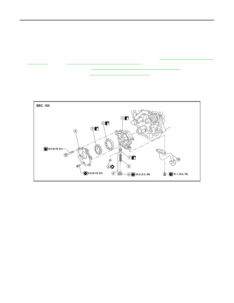
Before assembly, apply new engine oil to the parts as shown.

DISASSEMBLY

1. Remove the oil pump cover.
2. Remove inner rotor and outer rotor from oil pump housing.

CAUTION:

The outer rotor has directional vanes in relation to the rotation of the oil pump shaft. Note the

outer rotor vane direction for assembly.

3. Remove oil strainer from oil pump housing.
4. After removing regulator plug, remove spring and regulator valve.

INSPECTION AFTER DISASSEMBLY

Clearance of Oil Pump Parts

AWBIA1641ZZ

1.

Oil pump housing

2.

Oil pump outer rotor

3.

Oil pump inner rotor

4.

Oil pump cover

5.

Regulator valve O-ring

6.

Regulator valve set

7.

Regulator valve

8.

Regulator valve spring

9.

Regulator valve plug

10. Oil strainer

OIL PUMP

LU-13

< REMOVAL AND INSTALLATION >

C

D

E

F

G

H

I

J

K

L

M

A

LU

N

P

O

• Measure clearance with feeler gauge.

• Clearance between outer rotor and oil pump body (position 1).

• Tip clearance between inner rotor and outer rotor (position 2).

• Measure clearance with feeler gauge and straightedge.

• Side clearance between inner rotor and oil pump body (position 3).

• Side clearance between outer rotor and oil pump body (position 4).

• Calculate the clearance between inner rotor and oil pump body as follows:
1. Measure the outer diameter of protruded portion of inner rotor

(position A).

2. Measure the inner diameter of oil pump body with inside

micrometer (position B).

(clearance 5) = (inner diameter of oil pump body B) – (outer

diameter of inner rotor A)

3. If out of specifications, replace oil pump assembly.

Regulator Valve 

1. Visually inspect components for wear and damage.
2. Check oil pressure regulator valve sliding surface and valve

spring.

3. Coat regulator valve with engine oil. Check that it falls smoothly

into the valve hole by its own weight.

If damaged, replace oil pump assembly.   

Regulator Valve Clearance

Standard

LU-17, "Oil Pump"

Standard

LU-17, "Oil Pump"

SLC932A

Standard

LU-17, "Oil Pump"

Standard

LU-17, "Oil Pump"

SLC933A

Standard

LU-17, "Oil Pump"

SLC934AB

SLC251B

LU-14

< REMOVAL AND INSTALLATION >

OIL PUMP

(Clearance 6) = D (Valve hole diameter) – E (Outer diameter of

valve)

If it exceeds the standard, replace the oil pump assembly.

CAUTION:

• Coat regulator valve with engine oil.

• Check that it falls smoothly into the valve hole by its own

weight.

Assembly

Assembly is in the reverse order of disassembly.

• Assemble the outer rotor in the correct vane orientation to rotation

as noted during disassembly and the inner rotor with the groove on

the oil pump cover side.

CAUTION:

• Do not reuse O-ring.

• Before assembly apply new engine oil to the parts as speci-

fied.

Standard

: 

LU-17, "Regulator Valve"

SLC935AA

SLC324B

OIL COOLER

LU-15

< REMOVAL AND INSTALLATION >

C

D

E

F

G

H

I

J

K

L

M

A

LU

N

P

O

OIL COOLER

Removal and Installation

INFOID:0000000009177970

WARNING:

Be careful not to burn yourself, as the engine oil may be hot.

CAUTION:

• When removing oil cooler, prepare a shop cloth to absorb any engine oil leaks or spillage.

• Completely wipe off any engine oil that adheres to the engine and the vehicle.

NOTE:

When removing components such as hoses, tubes/lines, etc., cap or plug openings to prevent fluid from spill-

ing.

AWBIA1199GB

1.

Connector bolt

2.

Copper gasket

3.

Water drain plug

4.

Water pipe

5.

Bracket

6.

Clamp

7.

Water hose

8.

Relief valve

9.

Oil cooler O-Ring

10. Oil cooler

11.

Connector bolt

12. Oil filter

13. Water hose

14.

Water pipe

15. Water hose

A.

To water connector

B.

Refer to 

LU-10, "Removal and In-

stallation"

: Engine front

 Sealing point


Content   ..  837  838  839  840   ..