Nissan Pathfinder. Manual - part 707


  Index      Nissan     Nissan Pathfinder (2014 year) - Service and Repair Manual


Search            


Content   ..  705  706  707  708   ..


Nissan Pathfinder. Manual - part 707


B2581, B2582 INTAKE SENSOR

HAC-89

< DTC/CIRCUIT DIAGNOSIS >

[AUTOMATIC AIR CONDITIONING]

C

D

E

F

G

H

J

K

L

M

A

B

HAC

N

O

P

B2581, B2582 INTAKE SENSOR

DTC Logic

INFOID:0000000009176827

DTC DETECTION LOGIC 

NOTE:

• If DTC is displayed along with DTC U1000, first perform the trouble diagnosis for DTC U1000. Refer to 

HAC-

81, "DTC Logic"

.

• If DTC is displayed along with DTC U1010, first perform the trouble diagnosis for DTC U1010. 

HAC-82,

"DTC Logic"

.

DTC CONFIRMATION PROCEDURE

1.

PERFORM DTC CONFIRMATION PROCEDURE

With CONSULT

1. Turn ignition switch ON.

2. Using CONSULT, perform “SELF-DIAGNOSIS RESULTS” of HVAC. 

3. Check if any DTC No. is displayed in the self-diagnosis results. 
Is DTC detected?

YES

>> Refer to 

HAC-89, "Diagnosis Procedure"

.

NO

>> Inspection End.

Diagnosis Procedure

INFOID:0000000009176828

Regarding Wiring Diagram information, refer to 

HAC-49, "Wiring Diagram"

.

1.

CHECK INTAKE SENSOR POWER SUPPLY

1. Turn ignition switch OFF.

2. Disconnect intake sensor connector.

3. Turn ignition switch ON.

4. Check voltage between intake sensor harness connector and ground.

Is the inspection result normal?

YES

>> GO TO 2.

NO

>> GO TO 4.

2.

CHECK INTAKE SENSOR GROUND CIRCUIT

1. Turn ignition switch OFF.

2. Check continuity between intake sensor harness connector and ground.
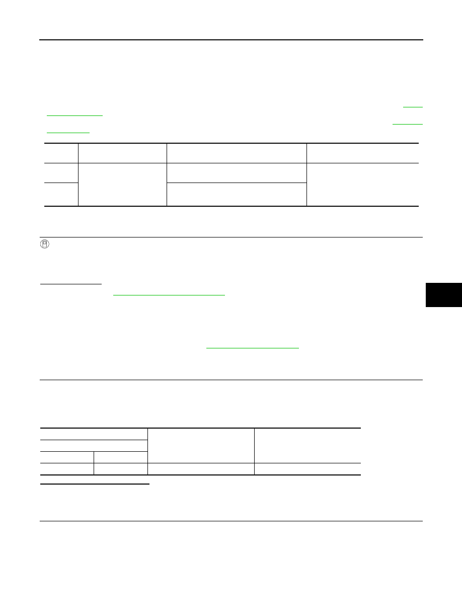
DTC

Items

(CONSULT screen terms)

DTC detection condition

Possible cause

B2581

INTAKE SENSOR

The intake sensor recognition temperature is 
too high.

• Intake sensor
• A/C auto amp.
• Harness or connectors

(The sensor circuit is open or short-
ed.)

B2582

The intake sensor recognition temperature is 
too low.

+

Voltage

(Approx.)

Intake sensor

Connector

Terminal

M103

1

Ground

5 V

HAC-90

< DTC/CIRCUIT DIAGNOSIS >

[AUTOMATIC AIR CONDITIONING]

B2581, B2582 INTAKE SENSOR

Is the inspection result normal?

YES

>> GO TO 3.

NO

>> Repair harness or connector.

3.

CHECK INTAKE SENSOR

Check intake sensor. Refer to 

HAC-90, "Component Inspection"

.

Is the inspection result normal?

YES

>> Replace A/C auto amp. Refer to 

HAC-157, "Removal and Installation"

.

NO

>> Replace intake sensor. Refer to 

HAC-161, "Removal and Installation"

.

4.

CHECK INTAKE SENSOR POWER SUPPLY CIRCUIT FOR OPEN

1. Turn ignition switch OFF.

2. Disconnect A/C auto amp. connector.

3. Check continuity between intake sensor harness connector and A/C auto amp. harness connector.

Is the inspection result normal?

YES

>> GO TO 5.

NO

>> Repair harness or connector.

5.

CHECK INTAKE SENSOR POWER SUPPLY CIRCUIT FOR GROUND SHORT

Check continuity between intake sensor harness connector and ground.

Is the inspection result normal?

YES

>> GO TO 6.

NO

>> Repair harness or connector.

6.

CHECK INTAKE SENSOR POWER SUPPLY CIRCUIT FOR POWER SHORT

1. Turn ignition switch ON.

2. Check voltage between intake sensor harness connector and ground.

Is the inspection result normal?

YES

>> Replace A/C auto amp. Refer to 

HAC-157, "Removal and Installation"

.

NO

>> Repair harness or connector.

Component Inspection

INFOID:0000000009176829

1.

CHECK INTAKE SENSOR

1. Turn ignition switch OFF.

2. Disconnect intake sensor connector.

Intake sensor

Continuity

Connector

Terminal

M103

2

Ground

Yes

Intake sensor

A/C auto amp.

Continuity

Connector

Terminal

Connector

Terminal

M103

1

M50

28

Yes

Intake sensor

Continuity

Connector

Terminal

M103

1

Ground

No

+

Voltage

(Approx.)

Intake sensor

Connector

Terminal

M103

1

Ground

0 V

B2581, B2582 INTAKE SENSOR

HAC-91

< DTC/CIRCUIT DIAGNOSIS >

[AUTOMATIC AIR CONDITIONING]

C

D

E

F

G

H

J

K

L

M

A

B

HAC

N

O

P

3. Check resistance between intake sensor terminals.

Is the inspection result normal?

YES

>> Inspection End.

NO

>> Replace intake sensor. Refer to 

HAC-161, "Removal and Installation"

.

Terminal

Condition

Resistance: k

Temperature: 

°C (°F)

1

2

−15 (5)

17.73

−10 (14)

13.46

−5 (23)

10.33

0 (32)

8.00

5 (41)

6.25

10 (50)

4.93

15 (59)

3.92

20 (68)

3.14

25 (77)

2.54

30 (86)

2.06

35 (95)

1.69

40 (104)

1.39

45 (113)

1.15

HAC-92

< DTC/CIRCUIT DIAGNOSIS >

[AUTOMATIC AIR CONDITIONING]

B2630, B2631 SUNLOAD SENSOR

B2630, B2631 SUNLOAD SENSOR

DTC Logic

INFOID:0000000009176830

DTC DETECTION LOGIC

NOTE:

• If DTC is displayed along with DTC U1000 or U1010, first diagnose the DTC U1000 or U1010. Refer to 

HAC-

81, "DTC Logic"

 or 

HAC-82, "DTC Logic"

• Sunload sensor may register a malfunction when indoors, at dusk, or at other times when light is insufficient.

When performing the diagnosis indoors, light the sunload sensor with a lamp (60W or more).

DTC CONFIRMATION PROCEDURE

1.

CHECK WITH SELF-DIAGNOSIS FUNCTION OF CONSULT

1. Using CONSULT, perform “SELF-DIAGNOSIS RESULTS” of HVAC. 

2. Check if any DTC No. is displayed in the self-diagnosis results. 

NOTE:

• If DTC is displayed along with DTC U1000 or U1010, first diagnose the DTC U1000 or U1010. Refer to 

HAC-

81, "DTC Logic"

 or 

HAC-82, "DTC Logic"

• Sunload sensor may register a malfunction when indoors, at dusk, or at other times when light is insufficient.

When performing the diagnosis indoors, light the sunload sensor with a lamp (60W or more).

Is DTC No.“B2630” or “B2631” displayed?

YES

>> Perform trouble diagnosis for the sunload sensor. Refer to 

HAC-92, "Diagnosis Procedure"

NO

>> Inspection End.

Diagnosis Procedure

INFOID:0000000009176831

Regarding Wiring Diagram information, refer to 

HAC-49, "Wiring Diagram"

.

1.

CHECK SUNLOAD SENSOR POWER SUPPLY

1. Disconnect sunload sensor connector.

2. Turn ignition switch ON.

3. Check voltage between sunload sensor harness connector M101 terminal 1 and ground.

Is the inspection result normal?

YES

>> GO TO 2.

NO

>> GO TO 4.

2.

CHECK CONTINUITY BETWEEN SUNLOAD SENSOR AND A/C AUTO AMP.

1. Turn ignition switch OFF.

2. Disconnect A/C auto amp. connector.

DTC

Items

 (CONSULT screen terms)

Diagnostic item is detected when...

Possible cause

B2630

SUNLOAD SEN (SHORT)

Detected calorie at sunload sensor 1395 w/m

2


(1200 kcal/m

2

·h) or more

• Sunload sensor
• A/C auto amp.
• Harness and connector

(Sunload sensor circuit is open, or 
there is a short in the circuit)

B2631

SUNLOAD SEN (OPEN)

Detected calorie at sunload sensor 0 w/m

2


(0 kcal/m

2

·h) 

+

Voltage

(Approx.)

Sunload sensor

Connector

Terminal

M101

1

Ground

5 V


Content   ..  705  706  707  708   ..