Nissan Pathfinder. Manual - part 642


  Index      Nissan     Nissan Pathfinder (2014 year) - Service and Repair Manual


Search            


Content   ..  640  641  642  643   ..


Nissan Pathfinder. Manual - part 642


FL-24

< DISASSEMBLY AND ASSEMBLY >

FUEL LEVEL SENSOR UNIT

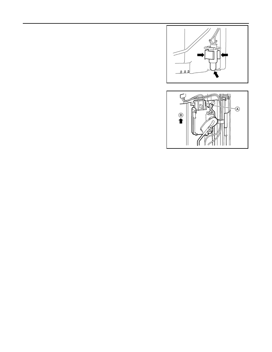
2. Release the two clips and remove the fuel tank temperature

sensor from the pump assembly.

3. Release the tab (A) and slide the fuel level sensor unit and float

arm assembly (B) up to remove.

Assembly

NOTE:

Assembly is the reverse order of disassembly.

• Ensure proper placement of the wires to the correct terminals and correct wire routing to the terminals.

• After connecting terminals, ensure they are securely locked and can not be pulled out.

• When installing the fuel level sensor unit, push down until the tab is locked into place.

ALBIA0670ZZ

ALBIA0749ZZ

SERVICE DATA AND SPECIFICATIONS (SDS)

FL-25

< SERVICE DATA AND SPECIFICATIONS (SDS) 

C

D

E

F

G

H

I

J

K

L

M

A

FL

N

P

O

SERVICE DATA AND SPECIFICATIONS (SDS)

SERVICE DATA AND SPECIFICATIONS (SDS)

Fuel Tank

INFOID:0000000009178415

Standard and Limit

Fuel tank capacity

Approx. 74.0   (19-1/2 US gal, 16-1/4 Imp gal)

Fuel recommendation

Refer to 

MA-15, "FOR USA AND CANADA : Fluids and Lubri-

cants"

 (United States and Canada) or 

MA-16, "FOR MEXICO : Flu-

ids and Lubricants"

 (Mexico).

FSU-1

SUSPENSION

C

D

F

G

H

I

J

K

L

M

SECTION 

FSU

A

B

FSU

N

O

P

CONTENTS

FRONT SUSPENSION

PRECAUTION ...............................................

2

PRECAUTIONS ...................................................

2

Precaution for Supplemental Restraint System 
(SRS) "AIR BAG" and "SEAT BELT PRE-TEN-
SIONER" .................................................................
..

2

Precaution for Procedure without Cowl Top Cover ......

2

Precautions for Suspension ......................................

2

SYMPTOM DIAGNOSIS  ...............................

3

NOISE, VIBRATION AND HARSHNESS 
(NVH) TROUBLESHOOTING  .............................

3

NVH Troubleshooting Chart  ......................................

3

PREPARATION ............................................

4

PREPARATION ...................................................

4

Special Service Tool  .................................................

4

Commercial Service Tool  ..........................................

4

PERIODIC MAINTENANCE ..........................

5

FRONT SUSPENSION ASSEMBLY  ...................

5

Inspection and Adjustment ........................................

5

REMOVAL AND INSTALLATION ................

7

FRONT COIL SPRING AND STRUT  ..................

7

Exploded View  ..........................................................

7

Removal and Installation ...........................................

7

Disposal ....................................................................

8

TRANSVERSE LINK .........................................

10

Exploded View .........................................................

10

Removal and Installation  .........................................

10

FRONT STABILIZER  ........................................

12

Exploded View .........................................................

12

Removal and Installation  .........................................

12

STEERING KNUCKLE ......................................

14

Exploded View .........................................................

14

Removal and Installation  .........................................

14

UNIT REMOVAL AND INSTALLATION ......

15

FRONT SUSPENSION MEMBER .....................

15

Exploded View .........................................................

15

Removal and Installation  .........................................

15

Inspection ................................................................

15

UNIT DISASSEMBLY AND ASSEMBLY  ....

16

FRONT COIL SPRING AND STRUT  ................

16

Disassembly and Assembly .....................................

16

Inspection ................................................................

18

SERVICE DATA AND SPECIFICATIONS 
(SDS) ............................................................

19

SERVICE DATA AND SPECIFICATIONS 
(SDS) .................................................................

19

Wheel Alignment  .....................................................

19

Ball Joint  ..................................................................

20

Wheelarch Height  ....................................................

20

FSU-2

< PRECAUTION >

PRECAUTIONS

PRECAUTION

PRECAUTIONS

Precaution for Supplemental Restraint System (SRS) "AIR BAG" and "SEAT BELT 
PRE-TENSIONER"

INFOID:0000000009726872

The Supplemental Restraint System such as “AIR BAG” and “SEAT BELT PRE-TENSIONER”, used along

with a front seat belt, helps to reduce the risk or severity of injury to the driver and front passenger for certain

types of collision. Information necessary to service the system safely is included in the SR and SB section of

this Service Manual.

WARNING:

• To avoid rendering the SRS inoperative, which could increase the risk of personal injury or death in

the event of a collision which would result in air bag inflation, all maintenance must be performed by

an authorized NISSAN/INFINITI dealer.

• Improper maintenance, including incorrect removal and installation of the SRS, can lead to personal

injury caused by unintentional activation of the system. For removal of Spiral Cable and Air Bag

Module, see the SR section.

• Do not use electrical test equipment on any circuit related to the SRS unless instructed to in this

Service Manual. SRS wiring harnesses can be identified by yellow and/or orange harnesses or har-

ness connectors.

PRECAUTIONS WHEN USING POWER TOOLS (AIR OR ELECTRIC) AND HAMMERS

WARNING:

• When working near the Airbag Diagnosis Sensor Unit or other Airbag System sensors with the Igni-

tion ON or engine running, DO NOT use air or electric power tools or strike near the sensor(s) with a

hammer. Heavy vibration could activate the sensor(s) and deploy the air bag(s), possibly causing

serious injury.

• When using air or electric power tools or hammers, always switch the Ignition OFF, disconnect the

battery and wait at least three minutes before performing any service.

Precaution for Procedure without Cowl Top Cover

INFOID:0000000009177362

When performing the procedure after removing cowl top cover, cover

the lower end of windshield with urethane, etc to prevent damage to

windshield.

Precautions for Suspension

INFOID:0000000009177363

• When installing rubber bushings, the final tightening must be carried out under unladen conditions with tires

on ground. Spilled oil might shorten the life of rubber bushings. Be sure to wipe off any spilled oil.

- Unladen conditions mean that fuel, engine coolant and lubricant are full. Spare tire, jack, hand tools and

mats are in designated positions.

• After servicing suspension parts, be sure to check wheel alignment.

• Self-lock nuts are not reusable. Always use new ones when installing. Since new self-lock nuts are pre-oiled,

tighten as they are. 

PIIB3706J


Content   ..  640  641  642  643   ..