Nissan Pathfinder. Manual - part 637


  Index      Nissan     Nissan Pathfinder (2014 year) - Service and Repair Manual


Search            


Content   ..  635  636  637  638   ..


Nissan Pathfinder. Manual - part 637


FL-4

< PREPARATION >

PREPARATION

PREPARATION

PREPARATION

Special Service Tool

INFOID:0000000009178397

The actual shape of Kent-Moore tools may differ from those of special service tools illustrated here.

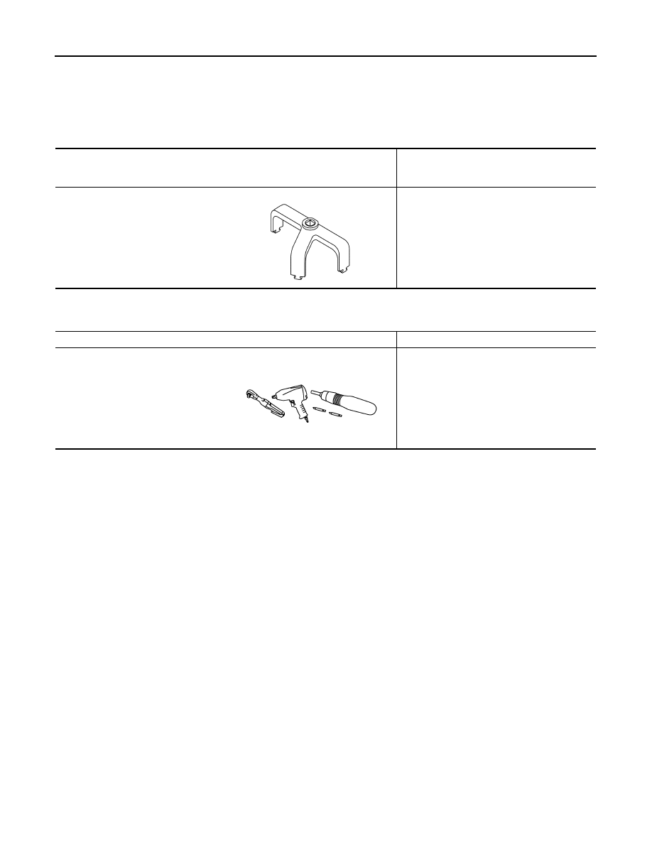
Commercial Service Tool

INFOID:0000000009178398

Tool number
(Kent-Moore No.)
Tool name

Description

( — )
(J-45747)
Fuel tank lock ring wrench

Removing and installing fuel tank lock ring

JSBIA1952ZZ

Tool name

Description

Power tool

Loosening nuts, screws and bolts

PIIB1407E

FUEL SYSTEM

FL-5

< PERIODIC MAINTENANCE >

C

D

E

F

G

H

I

J

K

L

M

A

FL

N

P

O

PERIODIC MAINTENANCE

FUEL SYSTEM

Inspection

INFOID:0000000009178399

Inspect fuel lines, filler cap and tank for improper attachment, leaks,

cracks, damage, loose connections, chafing or deterioration. Repair

or replace damaged parts as necessary.

Quick Connector

INFOID:0000000009178400

CAUTION:

• After connecting fuel tube quick connectors, make sure quick

connectors are secure.

Ensure that connector and resin tube do not contact any adja-

cent parts.

SMA803A

SBIA0504E

FL-6

< REMOVAL AND INSTALLATION >

FUEL LEVEL SENSOR UNIT, FUEL FILTER AND FUEL PUMP ASSEMBLY

REMOVAL AND INSTALLATION

FUEL LEVEL SENSOR UNIT, FUEL FILTER AND FUEL PUMP ASSEMBLY

Exploded View

INFOID:0000000009178401

Removal and Installation

INFOID:0000000009178402

NOTE:

When removing components such as hoses, tubes/lines, etc., cap or plug openings to prevent fluid from spill-

ing.

REMOVAL

WARNING:

1.

Lock ring

2.

Fuel level sensor, fuel filter and fuel 
pump assembly

3.

O-ring

4.

Fuel tank

Front

AWBIA1642ZZ

FUEL LEVEL SENSOR UNIT, FUEL FILTER AND FUEL PUMP ASSEMBLY

FL-7

< REMOVAL AND INSTALLATION >

C

D

E

F

G

H

I

J

K

L

M

A

FL

N

P

O

Read “General Precautions” before working on the fuel system. Refer to 

FL-2, "General Precaution"

1. Unscrew the fuel filler cap to release the pressure inside the fuel tank.
2. Release the fuel pressure from the fuel lines. Refer to 

EC-151, "Work Procedure"

.

3. Disconnect the battery negative terminal. Refer to 

PG-90, "Removal and Installation"

.

4. Remove both second row (LH) bench seat front slide covers. Refer to 

SE-91, "Exploded View"

.

5. Position the second row (LH) bench seat to full forward position.
6. Remove both second row (LH) bench seat rear slide covers. Refer to 

SE-91, "Exploded View"

.

7. Position and secure the carpet to gain access to the fuel pump inspection hole cover.

CAUTION:

Cover the immediate area surrounding the fuel pump inspection hole cover with plastic to avoid

gasoline damage to the carpet.

8. Remove the center floor duct (LH). Refer to 

VTL-13, "CENTER FLOOR DUCT : Removal and Installation

- Center Floor Duct"

.

9. Turn the four retainers (A) 90 degrees to disengage the clips

and remove the fuel pump inspection hole cover.

10. Disconnect the fuel level sensor, fuel filter, and fuel pump

assembly harness connector (A), EVAP hose connector (C), and

the fuel feed hose connector (B) from the fuel level sensor unit,

fuel filter, and fuel pump assembly.

Disconnect the quick connector as follows:

• Hold the sides of the connector, push in tabs and pull out the

tube.

• If the connector and the tube are stuck together, push and pull

several times until they start to move. Then disconnect them

by pulling.

CAUTION:

• The tube can be removed when the tabs are completely

depressed. Do not twist it more than necessary.

• Do not use any tools to remove the quick connector.

• Keep the resin tube away from heat. Be especially careful

when welding near the tube.

• Prevent acid liquid such as battery electrolyte, etc. from getting on the resin tube.

• Do not bend or twist the tube during installation and removal.

• Only when the tube is replaced, remove the remaining retainer on the tube or fuel level sensor,

fuel filter, and fuel pump assembly.

• When the tube or fuel level sensor, fuel filter, and fuel pump assembly is replaced, also replace

the retainer with a new one (green colored retainer).

: Front

ALBIA0781ZZ

: Front

ALBIA0782ZZ

SFE562A


Content   ..  635  636  637  638   ..