Nissan Pathfinder. Manual - part 633


  Index      Nissan     Nissan Pathfinder (2014 year) - Service and Repair Manual


Search            


Content   ..  631  632  633  634   ..


Nissan Pathfinder. Manual - part 633


FAX-20

< UNIT DISASSEMBLY AND ASSEMBLY >

FRONT DRIVE SHAFT

UNIT DISASSEMBLY AND ASSEMBLY

FRONT DRIVE SHAFT

Disassembly and Assembly (LH)

INFOID:0000000009177851

DISASSEMBLY

Transaxle Side

1. Mount front drive shaft in a vise.

CAUTION:

When mounting shaft in a vise, always use copper or aluminum plates between vise and shaft.

2. Remove boot bands and slide the boot back.
3. Remove circlip and dust shield from slide joint housing.
4. Put matching marks on slide joint housing and shaft before separating joint assembly.
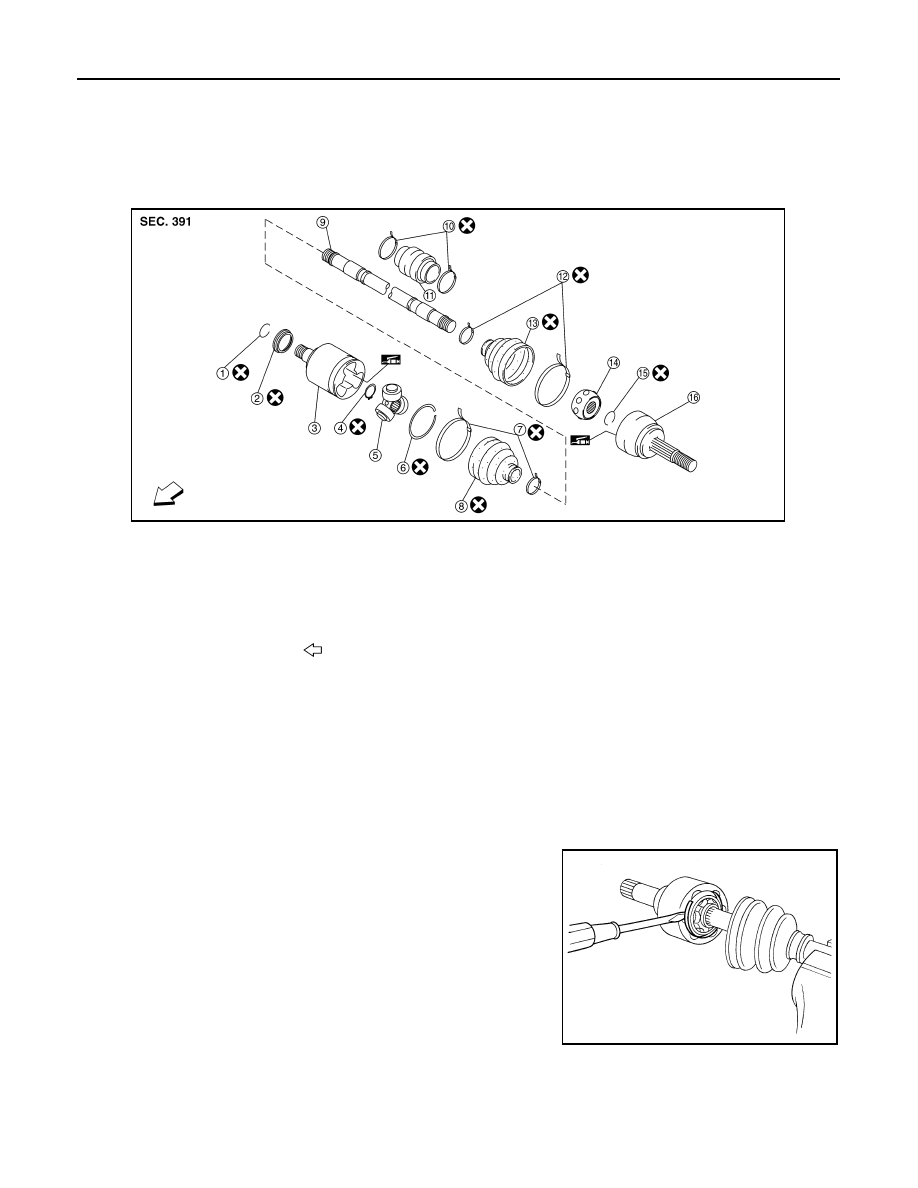
5. Remove stopper ring with a suitable tool, then pull out slide joint

housing.

1.

Circlip

2.

Dust shield

3.

Slide joint housing

4.

Snap ring

5.

Spider assembly

6.

Stopper ring

7.

Boot band

8.

Boot

9.

Shaft

10. Damper band

11. Damper

12. Boot band

13. Boot

14. Ball cage / Steel ball / Inner race assembly

15. Circlip

16. Joint sub-assembly

Front

AWDIA0896ZZ

SFA476

FRONT DRIVE SHAFT

FAX-21

< UNIT DISASSEMBLY AND ASSEMBLY >

C

E

F

G

H

I

J

K

L

M

A

B

FAX

N

O

P

6. Put matching marks on spider assembly and shaft.

7. Remove snap ring using a suitable tool, then remove spider

assembly from shaft.

8. Remove boot from shaft.
9. Clean the old grease off of the slide joint assembly.

Wheel Side

1. Mount the front drive shaft in a vise.

CAUTION:

When mounting shaft in a vise, always use copper or aluminum plates between vise and shaft.

2. Remove boot bands and slide the boot back.
3. Screw a sliding hammer or suitable tool 30 mm (1.18 in) or more

into threaded part of joint sub-assembly. Pull joint sub-assembly

out of shaft.

CAUTION:

• Align sliding hammer or suitable tool and drive shaft then

remove joint sub-assembly by pulling directly.

• If joint sub-assembly cannot be removed after five or

more unsuccessful attempts, replace the entire drive shaft

assembly.

4. Remove boot from shaft.
5. Remove circlip from shaft.
6. While rotating ball cage, clean the old grease off of the joint sub-assembly.

Damper

• Remove damper bands, then remove damper from shaft.

INSPECTION AFTER DISASSEMBLY

Shaft

• Replace shaft if there is bending, cracking, or other damage.

Joint Sub-Assembly

• Make sure there is no rough rotation or unusual axial looseness.

• Make sure there is no foreign material inside joint sub-assembly.

• Check joint sub-assembly for compression scars, cracks or fractures.

CAUTION:

If there are any irregular conditions of joint sub-assembly components, replace the entire joint sub-

assembly.

SFA963

SFA612

SDIA0606E

FAX-22

< UNIT DISASSEMBLY AND ASSEMBLY >

FRONT DRIVE SHAFT

Slide Joint Housing

• Make sure there are no compression scars, cracks or fractures or unusual wear of ball rolling surface.

• Make sure there is no damage to shaft screws.

• Make sure there is no deformation of boot installation parts.

Ball Cage

• Make sure there are no compression scars, cracks, fractures of sliding surface.

Steel Ball

• Make sure there are no compression scars, cracks, fractures or unusual wear.

Inner Race

• Check ball sliding surface for compression scars, cracks or fractures.

• Make sure there is no damage to serrated part.

CAUTION:

If there are any irregular conditions in the component, replace with a new set of joint sub-assembly,

ball cage, steel ball and inner race.

Damper

• Check damper for cracks or wear. Install damper with new damper bands.

ASSEMBLY

Transaxle Side

1. Install new boot and new small boot band on shaft.

CAUTION:

• Cover drive shaft serration with tape to prevent damage to

boot during installation.

2. Remove protective tape wound around serrated part of shaft.

3. Install spider assembly securely, making sure the matching marks which were made during disassembly

are properly aligned.

4. Install new snap ring using a suitable tool.
5. Pack drive shaft with specified amount of new grease (Genuine

NISSAN Grease or equivalent).

6. Install new stopper ring to housing of slide joint assembly.
7. After installation, pull shaft to check engagement between slide joint assembly and stopper ring.

SFA800

Grease quantity : Refer to 

FAX-31, "Drive Shaft"

.

SFA023A

FRONT DRIVE SHAFT

FAX-23

< UNIT DISASSEMBLY AND ASSEMBLY >

C

E

F

G

H

I

J

K

L

M

A

B

FAX

N

O

P

8. Install boot securely into grooves (indicated by * marks) as

shown.

CAUTION:

If there is grease on boot mounting surfaces (indicated by *

marks) of shaft and housing, boot may come off. Clean all

grease from surfaces.

9. Make sure boot installation length (L) is the length specified

below. Insert a suitable tool into the large end of boot. Bleed air

from boot to prevent boot deformation.

CAUTION:

• Boot may break if boot installation length is less than standard value.

• Be careful that suitable tool does not contact inside surface of boot.

10. Secure large and small ends of boot with new boot bands as

shown.

CAUTION:

Discard old boot bands and replace with new ones.

11. Install new dust shield to slide joint housing.
12. After installing housing and shaft, make sure boot position is correct. If boot position is not correct, remove

old boot bands then reposition the boot and secure with new boot bands.

Wheel Side

1. Insert the amount of grease (Genuine NISSAN Grease or equiv-

alent) into joint sub-assembly serration hole until grease begins

to ooze from ball groove and serration hole. After inserting

grease, use a shop cloth to wipe off old grease that has oozed

out.

2. Cover serrated part of shaft with tape. Install new boot band and

boot to shaft. Be careful not to damage boot.

CAUTION:

Discard old boot band and boot; replace with new one.

3. Remove protective tape wound around serrated part of shaft.

Boot installation 
length (L)

: Refer to 

FAX-31, "Drive 

Shaft"

.

JPDIF0144ZZ

SFA395

SDIA1127E

SFA800


Content   ..  631  632  633  634   ..