Nissan Pathfinder. Manual - part 578


  Index      Nissan     Nissan Pathfinder (2014 year) - Service and Repair Manual


Search            


Content   ..  576  577  578  579   ..


Nissan Pathfinder. Manual - part 578


EX-6

< REMOVAL AND INSTALLATION >

EXHAUST SYSTEM

• Be careful not to cut your hand on the insulator edge.

CAUTION:

Use genuine NISSAN exhaust system parts or equivalent, which are specifically designed for heat

resistance, corrosion resistance, and shape.

REMOVAL

Remove exhaust system components using power tool.

INSTALLATION

Installation is in the reverse order of removal.

Exhaust Manifold to Front Exhaust Tube

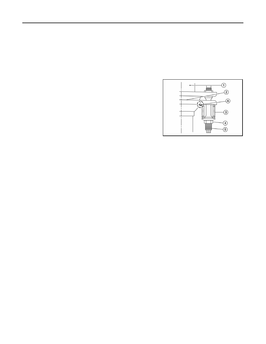
• Install the seal bearing (2) into the front exhaust tube (1).

• When installing the spring (3) and nut (4), check the following:

- Make sure the spring (3) sits properly on the flange surface by

aligning it to the locator dimples (A).

- Make sure the stud (5) does not contact the inside of the flange

bolt hole.

CAUTION:

Be careful not to damage seal bearing surface when install-

ing.

• Compact spring by tightening nut. 

CAUTION:

• Make sure springs are seated correctly on the flange and

not sitting on locator dimples (A). 

• Assemble the seal bearing so that the nut is located in the center of the flare flange hole without

contact with the flange.

CAUTION:

• Always replace exhaust gaskets with new ones when reassembling.

• If any insulator is badly deformed, repair or replace it. If deposits such as mud pile up on the insula-

tor, clean and inspect them.

• Temporarily tighten the nuts on the exhaust manifold side and the bolts on the vehicle side. Check

each part for interference with other components, and then tighten the nuts and bolts to specifica-

tion. 

INSPECTION AFTER INSTALLATION

• With the engine running, check the exhaust tube joints for exhaust gas leaks and unusual noises.

• Check that the mount brackets and mount insulators are installed properly and free from excessive stress.

Improper installation could result in excessive noise, leaks, and vibration. 

AWBIA1179ZZ

EXL-1

DRIVER CONTROLS

C

D

E

F

G

H

I

J

K

M

SECTION 

EXL

A

B

EXL

N

O

P

CONTENTS

EXTERIOR LIGHTING SYSTEM

PRECAUTION ...............................................

4

PRECAUTIONS ...................................................

4

Precaution for Supplemental Restraint System 
(SRS) "AIR BAG" and "SEAT BELT PRE-TEN-
SIONER" .................................................................
..

4

Precaution for Work  ..................................................

4

PREPARATION ............................................

5

PREPARATION ...................................................

5

Special Service Tool  .................................................

5

SYSTEM DESCRIPTION  ..............................

6

COMPONENT PARTS  ........................................

6

Component Parts Location ........................................

6

Component Description ............................................

7

SYSTEM ..............................................................

8

HEADLAMP SYSTEM  .................................................

8

HEADLAMP SYSTEM : System Diagram .................

8

HEADLAMP SYSTEM : System Description .............

8

AUTO LIGHT SYSTEM  ...............................................

8

AUTO LIGHT SYSTEM : System Diagram  ...............

9

AUTO LIGHT SYSTEM : System Description ...........

9

DAYTIME RUNNING LIGHT SYSTEM ........................

9

DAYTIME RUNNING LIGHT SYSTEM : System 
Diagram ...................................................................
..

9

DAYTIME RUNNING LIGHT SYSTEM : System 
Description ..............................................................

10

TURN SIGNAL AND HAZARD WARNING LAMP 
SYSTEM ....................................................................

10

TURN SIGNAL AND HAZARD WARNING LAMP 
SYSTEM : System Diagram ....................................

10

TURN SIGNAL AND HAZARD WARNING LAMP 
SYSTEM : System Description  ...............................

10

PARKING, LICENSE PLATE, SIDE MARKER AND 
TAIL LAMP SYSTEM .................................................

10

PARKING, LICENSE PLATE, SIDE MARKER 
AND TAIL LAMP SYSTEM : System Diagram  ........

10

PARKING, LICENSE PLATE, SIDE MARKER 
AND TAIL LAMP SYSTEM : System Description ....

11

FRONT FOG LAMP SYSTEM  ...................................

11

FRONT FOG LAMP SYSTEM : System Diagram ....

11

FRONT FOG LAMP SYSTEM : System Descrip-
tion ...........................................................................

11

TRAILER TOW SYSTEM ...........................................

12

TRAILER TOW SYSTEM : System Diagram ...........

12

TRAILER TOW SYSTEM : System Description  ......

12

DIAGNOSIS SYSTEM (BCM)  ...........................

13

COMMON ITEM  .........................................................

13

COMMON ITEM : CONSULT Function (BCM - 
COMMON ITEM)  .....................................................

13

HEADLAMP ...............................................................

14

HEADLAMP : CONSULT Function (BCM - HEAD-
LAMP) ......................................................................

14

FLASHER ...................................................................

15

FLASHER : CONSULT Function (BCM - FLASH-
ER) ..........................................................................

15

DIAGNOSIS SYSTEM (IPDM E/R)  ...................

16

Diagnosis Description ..............................................

16

CONSULT Function (IPDM E/R)  .............................

17

ECU DIAGNOSIS INFORMATION ..............

20

BCM, IPDM E/R .................................................

20

List of ECU Reference .............................................

20

WIRING DIAGRAM ......................................

21

HEADLAMP ......................................................

21

Wiring Diagram ........................................................

21

EXL-2

DAYTIME LIGHT SYSTEM ................................

29

Wiring Diagram  .......................................................

29

AUTO LIGHT SYSTEM ......................................

40

Wiring Diagram  .......................................................

40

FRONT FOG LAMP SYSTEM  ...........................

48

Wiring Diagram  .......................................................

48

TURN SIGNAL AND HAZARD WARNING 
LAMP SYSTEM  .................................................

56

Wiring Diagram  .......................................................

56

PARKING, LICENSE PLATE AND TAIL 
LAMPS SYSTEM  ...............................................

64

Wiring Diagram  .......................................................

64

STOP LAMP  ......................................................

76

Wiring Diagram  .......................................................

76

BACK-UP LAMP ................................................

80

Wiring Diagram  .......................................................

80

TRAILER TOW  ..................................................

90

Wiring Diagram  .......................................................

90

BASIC INSPECTION ..................................

103

DIAGNOSIS AND REPAIR WORKFLOW .......

103

Work Flow ..............................................................

103

DTC/CIRCUIT DIAGNOSIS ........................

106

POWER SUPPLY AND GROUND CIRCUIT  ...

106

BCM (BODY CONTROL MODULE)  ........................

106

BCM (BODY CONTROL MODULE) : Diagnosis 
Procedure ..............................................................

106

IPDM E/R (INTELLIGENT POWER DISTRIBU-
TION MODULE ENGINE ROOM)  ............................

106

IPDM E/R (INTELLIGENT POWER DISTRIBU-
TION MODULE ENGINE ROOM) : Diagnosis Pro-
cedure ....................................................................

106

HEADLAMP (HI) CIRCUIT  ..............................

108

Description .............................................................

108

Component Function Check  ..................................

108

Diagnosis Procedure  .............................................

108

HEADLAMP (LO) CIRCUIT  .............................

110

Description .............................................................

110

Component Function Check  ..................................

110

Diagnosis Procedure  .............................................

110

DAYTIME LIGHT RELAY CIRCUIT .................

112

Description .............................................................

112

Diagnosis Procedure  .............................................

112

Component Inspection ...........................................

113

FRONT FOG LAMP CIRCUIT  .........................

115

Description .............................................................

115

Component Function Check  ..................................

115

Diagnosis Procedure .............................................

115

PARKING LAMP CIRCUIT ...............................

117

Description ............................................................

117

Component Function Check  .................................

117

Diagnosis Procedure .............................................

117

TURN SIGNAL LAMP CIRCUIT .......................

121

Description ............................................................

121

Component Function Check  .................................

121

Diagnosis Procedure .............................................

121

OPTICAL SENSOR  ..........................................

124

Description ............................................................

124

Component Function Check  .................................

124

Diagnosis Procedure .............................................

124

HAZARD SWITCH ............................................

127

Component Function Check  .................................

127

Diagnosis Procedure .............................................

127

SYMPTOM DIAGNOSIS  ...........................

129

EXTERIOR LIGHTING SYSTEM SYMPTOMS ..

129

Symptom Table .....................................................

129

NORMAL OPERATING CONDITION ...............

131

Description ............................................................

131

BOTH SIDE HEADLAMPS DO NOT SWITCH 
TO HIGH BEAM ................................................

132

Description ............................................................

132

Diagnosis Procedure .............................................

132

BOTH SIDE HEADLAMPS (LO) ARE NOT 
TURNED ON .....................................................

133

Description ............................................................

133

Diagnosis Procedure .............................................

133

PARKING, LICENSE PLATE, SIDE MARKER 
AND TAIL LAMPS ARE NOT TURNED ON  ....

134

Description ............................................................

134

Diagnosis Procedure .............................................

134

BOTH SIDE FRONT FOG LAMPS ARE NOT 
TURNED ON .....................................................

135

Description ............................................................

135

Diagnosis Procedure .............................................

135

DAYTIME LIGHT SYSTEM INOPERATIVE  .....

136

Description ............................................................

136

Diagnosis Procedure .............................................

136

PERIODIC MAINTENANCE ......................

137

HEADLAMP ......................................................

137

Inspection ..............................................................

137

Aiming Adjustment Procedure ..............................

138

FRONT FOG LAMP AIMING ADJUSTMENT ..

140

Aiming Adjustment  ................................................

140

EXL-3

C

D

E

F

G

H

I

J

K

M

A

B

EXL

N

O

P

REMOVAL AND INSTALLATION .............

141

FRONT COMBINATION LAMP ........................

141

Exploded View  ......................................................

141

Removal and Installation .......................................

141

FRONT FOG LAMP ..........................................

144

Exploded View  ......................................................

144

Removal and Installation .......................................

144

OPTICAL SENSOR  ..........................................

146

Exploded View  ......................................................

146

Removal and Installation .......................................

146

LIGHTING & TURN SIGNAL SWITCH  ............

147

Removal and Installation .......................................

147

HAZARD SWITCH ............................................

148

Removal and Installation .......................................

148

REAR COMBINATION LAMP ..........................

149

Exploded View  ......................................................

149

Removal and Installation .......................................

149

HIGH-MOUNTED STOP LAMP ........................

151

Removal and Installation .......................................

151

BACK-UP LAMP  .............................................

152

Exploded View .......................................................

152

Removal and Installation  .......................................

152

LICENSE PLATE LAMP  .................................

153

Exploded View .......................................................

153

Removal and Installation  .......................................

153

UNIT DISASSEMBLY AND ASSEMBLY  ..

155

FRONT COMBINATION LAMP  ......................

155

Exploded View .......................................................

155

Disassembly and Assembly ...................................

155

REAR COMBINATION LAMP .........................

156

Exploded View .......................................................

156

Disassembly and Assembly ...................................

156

SERVICE DATA AND SPECIFICATIONS 
(SDS) ..........................................................

157

SERVICE DATA AND SPECIFICATIONS 
(SDS) ...............................................................

157

Bulb Specifications  ................................................

157


Content   ..  576  577  578  579   ..