Nissan Pathfinder. Manual - part 565


  Index      Nissan     Nissan Pathfinder (2014 year) - Service and Repair Manual


Search            


Content   ..  563  564  565  566   ..


Nissan Pathfinder. Manual - part 565


ENGINE MOUNT

EM-99

< REMOVAL AND INSTALLATION >

C

D

E

F

G

H

I

J

K

L

M

A

EM

N

P

O

ENGINE MOUNT

ENGINE MOUNT (FRONT)
ENGINE MOUNT (FRONT) : Removal and Installation

INFOID:0000000009177939

WARNING:

• Situate the vehicle on a flat and solid surface.

• Place chocks at front and back of rear wheels.

CAUTION:

• Always work safely. 

• Do not start work until the engine and exhaust system are cooled completely.

• Refer to the applicable sections for warnings, cautions, notes, and instructions if necessary proce-

dures are not included in this section.

NOTE:

When removing components such as hoses, tubes/lines, etc., cap or plug openings to prevent fluid from spill-

ing.

REMOVAL

1. Remove the air cleaner case (upper), air cleaner case (lower), front air duct, and air duct hose and reso-

nator assembly. Refer to 

EM-24, "Removal and Installation"

.

2. Remove the battery and battery tray assembly. Refer to 

PG-92, "Removal and Installation"

.

3. Remove the engine under cover. Refer to 

EXT-30, "Removal and Installation"

.

4. Remove the fender protector side covers (RH/LH). Refer to 

EXT-28, "FENDER PROTECTOR : Exploded

View"

5. Partially remove the fender protectors (RH/LH). Refer to 

EXT-28, "FENDER PROTECTOR : Removal and

Installation"

.

6. Remove the radiator assembly. Refer to 

CO-15, "Removal and Installation"

.

7. Remove the engine cooling fan shroud and motor assembly. Refer to 

CO-17, "Removal and Installation"

.

8. Remove the exhaust manifold heat shield (LH). Refer to 

EM-31, "Exploded View"

.

9. Support the engine with a suitable tool.
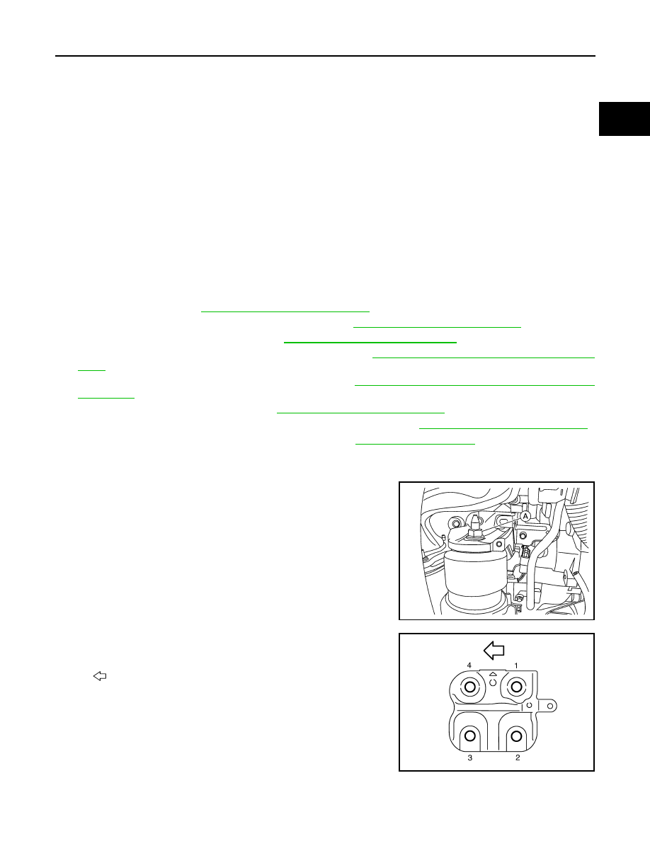
10. Disconnect the engine mount insulator (front) vacuum hose.
11. Remove the engine mount insulator (front) nut (A).

12. Loosen the engine mount bracket (front) bolts in the reverse

order shown. 

13. Remove the engine mount bracket (front). 

AWBIA1241GB

: Engine front

JPBIA1731ZZ

EM-100

< REMOVAL AND INSTALLATION >

ENGINE MOUNT

14. Remove the engine mount insulator (front) bolts in the reverse

order as shown. 

15. Remove the engine mount insulator (front).

INSTALLATION

CAUTION:

• Do not damage or spill engine oil on the engine mount insulator (front). 

• Check engine mount insulator (front) is seated properly before tightening. 
1. Install the engine mount insulator (front).

2. Install the engine mount insulator (front) bolts and tighten to

specification in the order shown. 

3. Install the engine mount bracket (front) to the engine block. 

: Front

JPBIA1735ZZ

AWBIA1242GB

AWBIA1242GB

: Front

Engine mount insulator (front) 
bolts

: 55 N·m (5.6 kg-m, 
41 ft-lb)

JPBIA1735ZZ

ENGINE MOUNT

EM-101

< REMOVAL AND INSTALLATION >

C

D

E

F

G

H

I

J

K

L

M

A

EM

N

P

O

4. Tighten the engine mount bracket (front) bolts to specification in

the order shown. 

5. Install the engine mount insulator (front) nut (A) and tighten to

specification.

6. Installation of the remaining components is in the reverse order of removal.

: Engine front

Engine mount bracket (front) 
bolts

: 40 N·m (4.1 kg-m, 
30 ft-lb)

JPBIA1731ZZ

Engine mount insulator (front) 
nut

: 103 N·m (11 kg-m, 
76 ft-lb)

AWBIA1241GB

EM-102

< UNIT REMOVAL AND INSTALLATION >

ENGINE ASSEMBLY

UNIT REMOVAL AND INSTALLATION

ENGINE ASSEMBLY

2WD
2WD : Exploded View

INFOID:0000000009177940

2WD : Removal and Installation

INFOID:0000000009177941

WARNING:

• Situate the vehicle on a flat and solid surface.

• Place chocks at front and back of rear wheels.

• For engines not equipped with engine slingers, attach proper slingers and bolts described in PARTS

CATALOG.

CAUTION:

• Always work safely. 

• Do not start work until the engine and exhaust system are cooled completely.

• Refer to the applicable sections for warnings, cautions, notes, and instructions if necessary proce-

dures are not included in the engine section.

AWBIA1639ZZ

1.

Gusset

2.

Rear torque rod

3.

Rear torque rod bracket

4.

Upper torque rod

5.

Engine mounting insulator (RH)

6.

Engine mounting bracket (RH)

7.

Engine mounting insulator (front)

8.

Engine mounting bracket (front)

9.

Vacuum hose

10. Vacuum tube (front)

11. Vacuum hose

12. Engine mounting insulator (LH)

13. Engine mounting insulator (rear)

14. Engine mounting bracket (rear)

15. Engine mounting stay (rear)

A.

To electronic controlled engine mount 
control solenoid valve

B.

To transaxle

Front


Content   ..  563  564  565  566   ..