Nissan Pathfinder. Manual - part 548
EXHAUST MANIFOLD AND THREE WAY CATALYST
EM-31
< REMOVAL AND INSTALLATION >
C
D
E
F
G
H
I
J
K
L
M
A
EM
N
P
O
EXHAUST MANIFOLD AND THREE WAY CATALYST
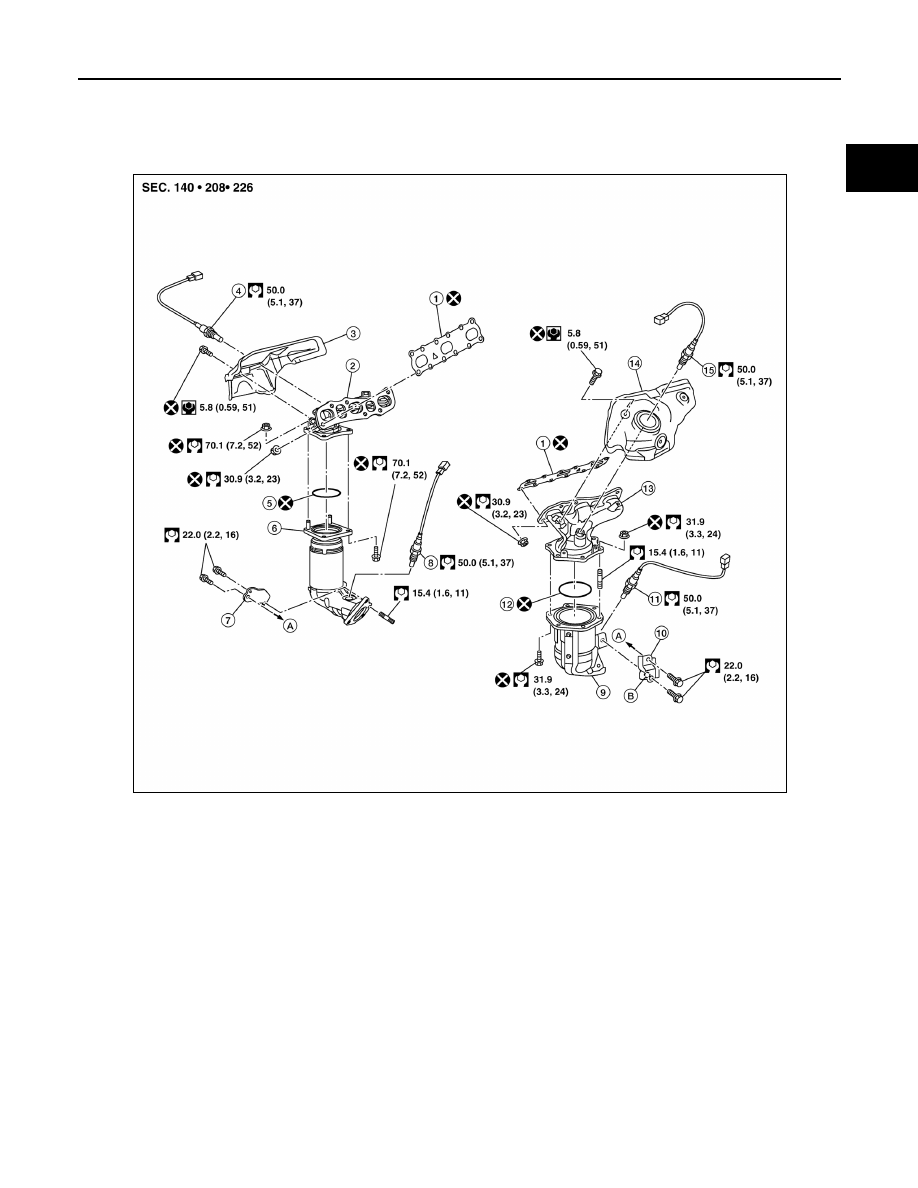
Exploded View
INFOID:0000000009177904
Removal and Installation (bank 2)
INFOID:0000000009177905
REMOVAL
WARNING:
• Perform the work when the exhaust system has completely cooled down.
• When removing the front and rear engine mount through bolts and nuts, lift the engine up slightly for
safety.
NOTE:
When removing components such as hoses, tubes/lines, etc., cap or plug openings to prevent fluid from spill-
ing.
1.
Gasket
2.
Exhaust manifold (bank 1)
3.
Exhaust manifold cover (bank 1)
4.
Air fuel ratio sensor 1 (bank 1)
5.
Ring gasket
6.
Three way catalyst (bank 1)
7.
Three way catalyst support (bank 1)
8.
Heated oxygen sensor 2 (bank 1)
9.
Three way catalyst (bank 2)
10. Three way catalyst support (bank 2)
11. Heated oxygen sensor 2 (bank 2)
12.
Ring gasket
13. Exhaust manifold (bank 2)
14. Exhaust manifold cover (bank 2)
15.
Air fuel ratio sensor 1 (bank 2)
A.
To oil pan (upper)
B.
Upper mark
AWBIA1356ZZ