Nissan Pathfinder. Manual - part 187
AV
SUBWOOFER
AV-575
< DTC/CIRCUIT DIAGNOSIS >
[PREMIUM AUDIO WITH NAVIGATION]
C
D
E
F
G
H
I
J
K
L
M
B
A
O
P
Is the inspection result normal?
YES
>> GO TO 8.
NO
>> Repair or replace harness or connectors.
8.
CHECK PRE-AMP SIGNAL
1. Connect AV control unit connector M161 and BOSE speaker amp. connector B130.
2. Turn ignition switch to ACC.
3. Push AV control unit POWER switch.
4. Check signal between the terminals of AV control unit connector M161.
Is the inspection result normal?
YES
>> Replace BOSE speaker amp. Refer to
AV-618, "Removal and Installation"
NO
>> Replace AV control unit. Refer to
AV-611, "Removal and Installation"
AV control unit
Ground
Continuity
Connector
Terminal
M161
4
—
No
5
13
14
AV control unit connector M161
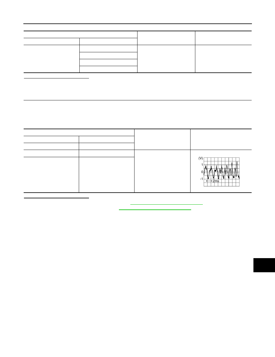
Condition
Reference value
(+)
(
−)
Terminal
Terminal
4
5
Audio signal output
13
14
SKIB3609E