Content .. 1214 1215 1216 1217 ..
Nissan Pathfinder. Manual - part 1216
WT-46
< DTC/CIRCUIT DIAGNOSIS >
C1730, C1731, C1732, C1733 FLAT TIRE
C1730, C1731, C1732, C1733 FLAT TIRE
DTC Logic
INFOID:0000000009177449
NOTE:
The Signal Tech II Tool (J-50190) can be used to perform the following functions. Refer to the Signal Tech II
User Guide for additional information.
• Activate and display TPMS transmitter IDs
• Display tire pressure reported by the TPMS transmitter
• Read TPMS DTCs
• Register TPMS transmitter IDs
DTC DETECTION LOGIC
DTC CONFIRMATION PROCEDURE
1.
PERFORM SELF DIAGNOSTIC RESULT
With CONSULT
1. Drive at a speed of 40 km/h (25 MPH) or more for 3 minutes, and then drive the vehicle at any speed for
10 minutes.
2. Perform Self Diagnostic Result.
Is DTC C1730, C1731, C1732, or C1733 detected?
YES
>> Proceed to
.
NO
>> Inspection End.
Diagnosis Procedure
INFOID:0000000009177450
NOTE:
The Signal Tech II Tool (J-50190) can be used to perform the following functions. Refer to the Signal Tech II
User Guide for additional information.
• Activate and display TPMS transmitter IDs
• Display tire pressure reported by the TPMS transmitter
• Read TPMS DTCs
• Register TPMS transmitter IDs
1.
TIRE PRESSURE SENSOR ID REGISTRATION
Perform tire pressure sensor ID registration. Refer to
.
Can the tire pressure sensor ID registration be completed?
YES
>> GO TO 2.
NO
>> Replace applicable tire pressure sensor. Refer to
WT-61, "Removal and Installation"
2.
CHECK TIRE PRESSURE
Check the air pressure of all wheels. Refer to
.
Is the inspection result normal?
YES
>> Perform DTC CONFIRMATION PROCEDURE again. Refer to
NO
>> GO TO 3.
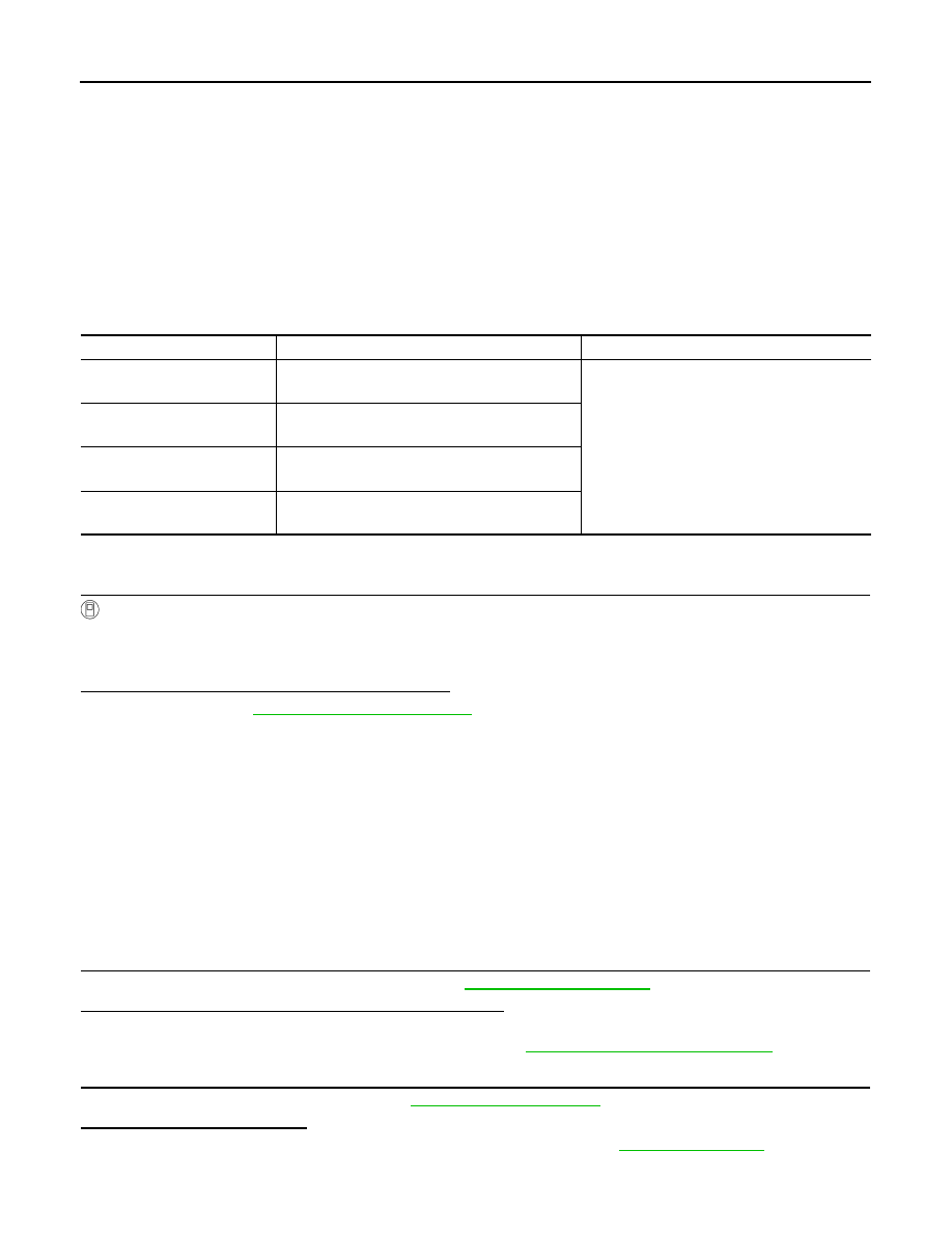
CONSULT Display
DTC Detection Condition
Possible Cause
FLAT TIRE FL
[C1730]
Front LH tire pressure is 70 kPa (0.7 kg/cm
2
, 10
psi) or less.
• Low tire pressure
• Tire pressure sensor
FLAT TIRE FR
[C1731]
Front RH tire pressure is 70 kPa (0.7 kg/cm
2
, 10
psi) or less.
FLAT TIRE RR
[C1732]
Rear RH tire pressure is 70 kPa (0.7 kg/cm
2
, 10
psi) or less.
FLAT TIRE RL
[C1733]
Rear LH tire pressure is 70 kPa (0.7 kg/cm
2
, 10
psi) or less.