Nissan Pathfinder. Manual - part 1189


  Index      Nissan     Nissan Pathfinder (2014 year) - Service and Repair Manual


Search            


Content   ..  1187  1188  1189  1190   ..


Nissan Pathfinder. Manual - part 1189


TRANSMISSION ASSEMBLY

TM-215

< UNIT REMOVAL AND INSTALLATION >

[CVT: RE0F10E]

C

E

F

G

H

I

J

K

L

M

A

B

TM

N

O

P

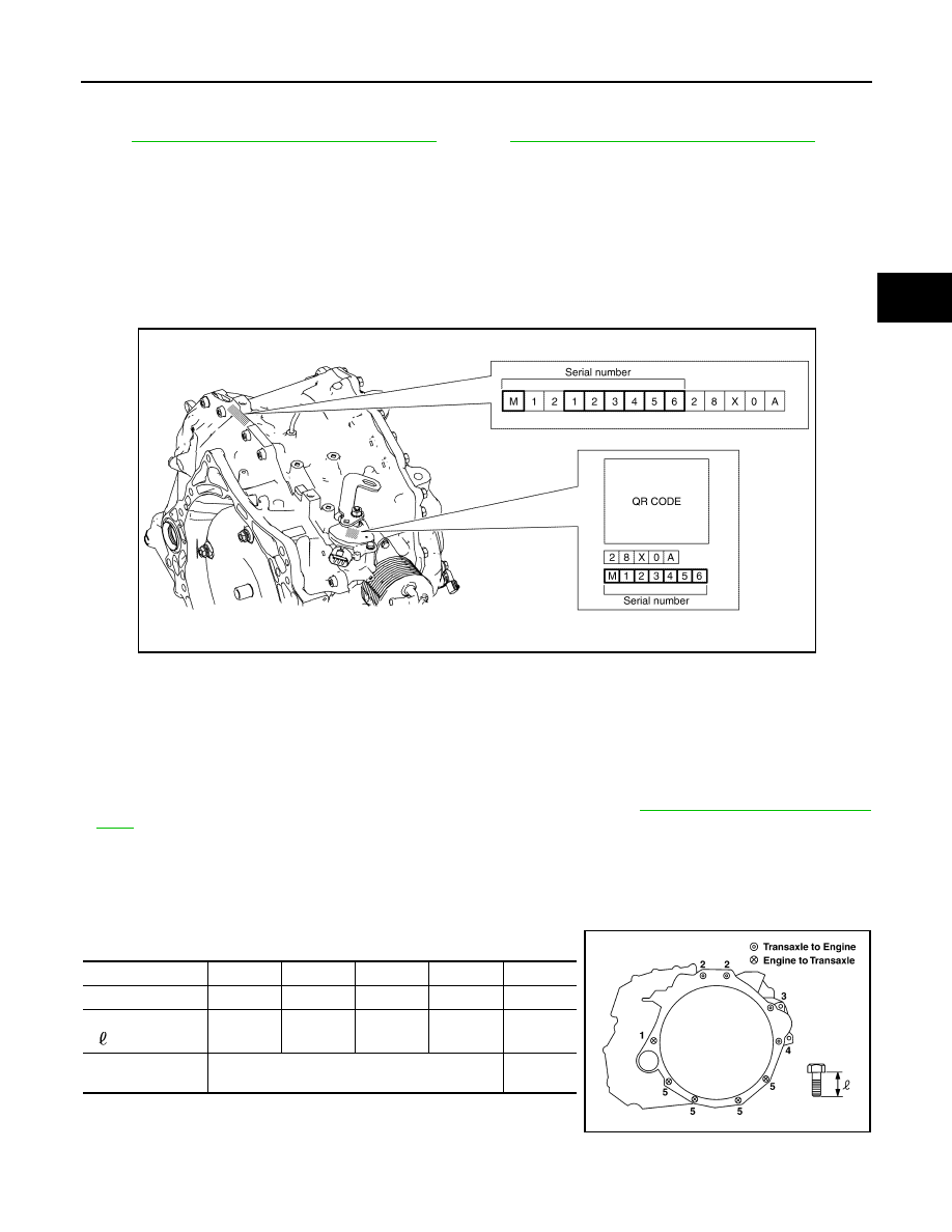
5. Remove the transaxle to engine and engine to transaxle bolts.
6. Separate the engine from the transaxle and remove the engine from the front suspension member. Refer

to 

EM-102, "2WD : Removal and Installation"

 (2WD) or 

EM-107, "4WD : Removal and Installation"

 (4WD).

NOTE:

Using paint, put matching marks on the drive plate and torque converter when removing the torque con-

verter to drive plate nuts.

7. Remove transmission bracket.
8. Lift the transaxle from the front suspension member.

INSTALLATION

Installation is in the reverse order of removal.

NOTE:

Write down the serial number of the new transaxle assembly.

CAUTION:

• When replacing an engine or transaxle you must make sure any dowels are installed correctly during

re-assembly

• Improper alignment caused by missing dowels may cause vibration, oil leaks or breakage of drive

train components.

• Do not reuse O-rings or copper sealing washers.

• When turning crankshaft, turn it clockwise as viewed from the front of the engine.

• When tightening the nuts for the torque converter while securing the crankshaft pulley bolt, be sure

to confirm the tightening torque of the crankshaft pulley bolt. Refer to 

EM-62, "Removal and Installa-

tion"

.

• After converter is installed to drive plate, rotate crankshaft several turns to check that CVT rotates

freely without binding.

• When installing the CVT to the engine, align the matching mark on the drive plate with the matching

mark on the torque converter.

When installing CVT assembly to the engine assembly, attach the bolts in accordance with

the following standard.

• When installing the drive plate to torque converter nuts, tighten

them temporarily. then tighten the nuts to the specified torque.

JSDIA3768GB

Bolt  No.

1

2

3

4

5

Number  of  bolts

1

2

1

1

4

Bolt length
“ ”mm  (in)

55 (2.17)

39 (1.54)

35 (1.38)

50 (1.97)

45 (1.77)

Tightening torque
N·m (kg-m, ft-lb)

74.5 (7.6, 55)

50.0

(5.1, 37)

AWDIA1031ZZ

TM-216

< UNIT REMOVAL AND INSTALLATION >

[CVT: RE0F10E]

TRANSMISSION ASSEMBLY

Inspection and Adjustment

INFOID:0000000009177690

INSPECTION BEFORE INSTALLATION

After inserting a torque converter to the CVT, check dimension (A)

with in the reference value limit.

INSPECTION AFTER INSTALLATION

Check the following items:

• CVT fluid leakage, refer to 

TM-185, "Inspection"

.

• For CVT position, refer to 

TM-88, "Inspection and Adjustment"

.

• Start the engine and check for coolant leakage from the parts which are removed and reinstalled.

ADJUSTMENT AFTER INSTALLATION

• Adjust the CVT fluid level. Refer to 

TM-187, "Adjustment"

.

• Perform "ADDITIONAL SERVICE WHEN REPLACE TRANSAXLE ASSEMBLY". Refer to 

TM-82, "Descrip-

tion"

.

B

:  Scale

C

: Straightedge

Dimension (A)

: Refer to 

TM-219, "Torque Converter"

.

JPDIA0115ZZ

TORQUE CONVERTER AND CONVERTER HOUSING OIL SEAL

TM-217

< UNIT DISASSEMBLY AND ASSEMBLY >

[CVT: RE0F10E]

C

E

F

G

H

I

J

K

L

M

A

B

TM

N

O

P

UNIT DISASSEMBLY AND ASSEMBLY

TORQUE CONVERTER AND CONVERTER HOUSING OIL SEAL

Exploded View

INFOID:0000000009177691

Disassembly

INFOID:0000000009177692

1. Remove transaxle assembly. Refer to 

TM-214, "Removal and Installation"

.

2. Remove torque converter from transaxle assembly.

CAUTION:

Do not damage the bushing on the inside of torque converter sleeve when removing torque con-

verter.

3. Remove converter housing oil seal using suitable tool.

CAUTION:

Be careful not to scratch converter housing.

Assembly

INFOID:0000000009177693

Assembly is in the reverse order of disassembly.

CAUTION:

Do not reuse converter housing oil seal.

NOTE:

Lubricate converter housing oil seal prior to installation.
• Drive converter housing oil seal   evenly using a drift (A) (com-

mercial service tool) so that converter housing oil seal protrudes by

the dimension (B) respectively.

Unit: mm (in)

Torque converter

O-ring

Converter housing oil seal

Transaxle assembly

: Always replace after every disassembly.

: Apply CVT fluid

JSDIA4173ZZ

Commercial service tool: (A)

Outer diameter: 65 (2.56)

Inner diameter: 60 (2.36)

: Transaxle assembly

SCIA7908J

TM-218

< UNIT DISASSEMBLY AND ASSEMBLY >

[CVT: RE0F10E]

TORQUE CONVERTER AND CONVERTER HOUSING OIL SEAL

Unit: mm (in)

NOTE:

Converter housing oil seal pulling direction is used as the refer-

ence.

• Attach the pawl   of the torque converter to the drive sprocket

hole   on the transaxle assembly side.

CAUTION:

• Rotate the torque converter for installing torque converter.

• Do not damage the bushing inside the torque converter

sleeve when installing the converter housing oil seal.

Inspection

INFOID:0000000009177694

INSPECTION AFTER INSTALLATION

• After inserting a torque converter to the CVT, check dimension (A)

with in the reference value limit.

Dimension (B)

1.0 

± 0.5 (0.039 ± 0.020)

SCIA7909J

SCIA7907J

B

:  Scale

C

: Straightedge

Dimension (A)

: Refer to 

TM-219, "Torque Converter"

.

JPDIA0115ZZ


Content   ..  1187  1188  1189  1190   ..