Content .. 1181 1182 1183 1184 ..
Nissan Pathfinder. Manual - part 1183
CONTROL CABLE
TM-191
< REMOVAL AND INSTALLATION >
[CVT: RE0F10E]
C
E
F
G
H
I
J
K
L
M
A
B
TM
N
O
P
CONTROL CABLE
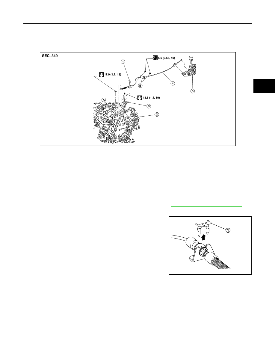
Exploded View
INFOID:0000000009177649
Removal and Installation
INFOID:0000000009177650
INSTALLATION
CAUTION:
Always apply the parking brake before performing removal and installation.
1. Remove the front air duct and air cleaner case assembly. Refer to
EM-24, "Removal and Installation"
.
2. Remove the control cable nut from the manual lever.
3. Remove the lock plate (1).
4. Remove center console upper side finisher (LH). Refer to
.
1.
Bracket B
2.
Lock plate
3.
Transaxle assembly
4.
Bracket A
5.
Control cable
6.
CVT shift selector assembly
A: Manual lever
B: Grommet
ALDIA0352GB
JSDIA1812ZZ