Nissan Pathfinder. Manual - part 1116


  Index      Nissan     Nissan Pathfinder (2014 year) - Service and Repair Manual


Search            


Content   ..  1114  1115  1116  1117   ..


Nissan Pathfinder. Manual - part 1116


POWER STEERING FLUID

ST-43

< PERIODIC MAINTENANCE >

C

D

E

F

H

I

J

K

L

M

A

B

ST

N

O

P

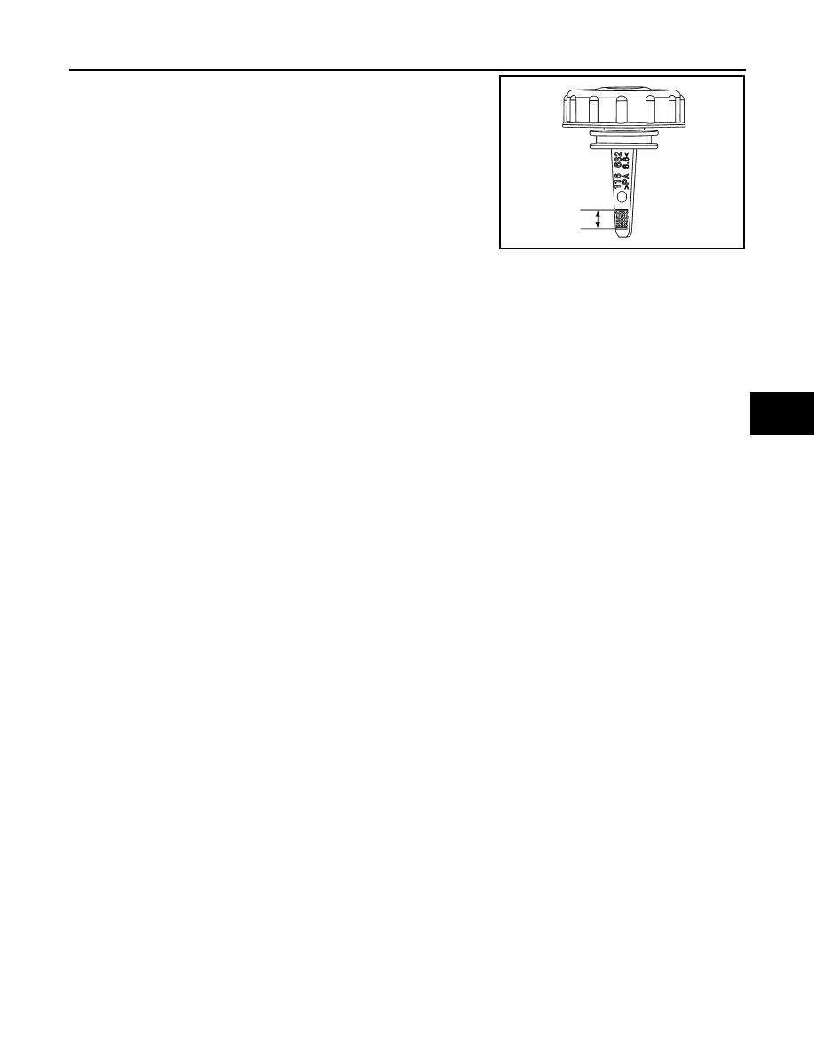
10. Verify proper power steering fluid level. Power steering fluid

level should be between the hatching area on the power steer-

ing reservoir cap indicator.

ALGIA0125ZZ

ST-44

< REMOVAL AND INSTALLATION >

STEERING WHEEL

REMOVAL AND INSTALLATION

STEERING WHEEL

Exploded View

INFOID:0000000009177101

Removal and Installation

INFOID:0000000009177102

REMOVAL

1. Set the front wheels and tires in the straight-ahead position.
2. Remove driver air bag module. Refer to 

SR-12, "Removal and Installation"

.

3. Remove steering wheel lock nut.
4. Remove steering switches. Refer to 

AV-48, "Removal and Installation"

 (BASE AUDIO), 

AV-190, "Removal

and Installation"

 (MID AUDIO WITH BOSE AUDIO), 

AV-368, "Removal and Installation"

 (MID AUDIO

WITHOUT BOSE AUDIO), 

AV-614, "Removal and Installation"

 (PREMIUM AUDIO WITH NAVIGATION).

5. Remove steering wheel using suitable tool.

CAUTION:

Place a piece of tape across the spiral cable so it will not be rotated out of position.

6. Inspect steering wheel near the puller holes for damage. Replace as necessary.

INSTALLATION

Installation is in the reverse order of removal.

• Align spiral cable correctly before installing steering wheel. Make sure that the spiral cable is in the neutral

position. Refer to 

SR-15, "Removal and Installation"

.

• Adjust the neutral position of the steering angle sensor. Refer to 

BRC-55, "Work Procedure"

.

• Tighten steering wheel center nut to specification. Refer to 

ST-44, "Exploded View"

.

CAUTION:

1.

Steering wheel

2.

Cover

3.

Steering switches

4.

Driver air bag module

A.

Refer to 

SR-12, "Exploded View"

.

Pawl

ALGIA0109GB

STEERING WHEEL

ST-45

< REMOVAL AND INSTALLATION >

C

D

E

F

H

I

J

K

L

M

A

B

ST

N

O

P

• The spiral cable may snap due to steering operation if the cable is not installed in the correct posi-

tion.

• With the steering linkage disconnected, the cable may snap by turning the steering wheel beyond

the limited number of turns.

ST-46

< REMOVAL AND INSTALLATION >

STEERING COLUMN

STEERING COLUMN

Exploded View

INFOID:0000000009177103

Removal and Installation

INFOID:0000000009177104

CAUTION:

• Any time the ignition switch has been disconnected, removed or installed, the keys must be re-regis-

tered in the BCM. Refer to CONSULT operations manual.

• Care must be taken not to give axial impact to steering column during removal and installation.

• Care must be taken not to move steering gear during removal of steering column.

REMOVAL

1. Remove the steering angle sensor from the steering column. Refer to 

BRC-126, "Removal and Installa-

tion"

.

2. Remove the combination switch. Refer to 

BCS-81, "Removal and Installation"

.

3. Remove the instrument lower panel LH. Refer to 

IP-25, "Removal and Installation"

.

4. Remove the instrument panel brace bolts and the instrument

panel brace.

5. Disconnect the tilt motor and telescopic motor harness connectors (if equipped).

1.

Steering column

2.

Hole cover

3.

Lower boot

4.

Steering intermediate shaft

AWGIA0299ZZ

ALGIA0108ZZ


Content   ..  1114  1115  1116  1117   ..