Content .. 1010 1011 1012 1013 ..
Nissan Pathfinder. Manual - part 1012
SE-46
< WIRING DIAGRAM >
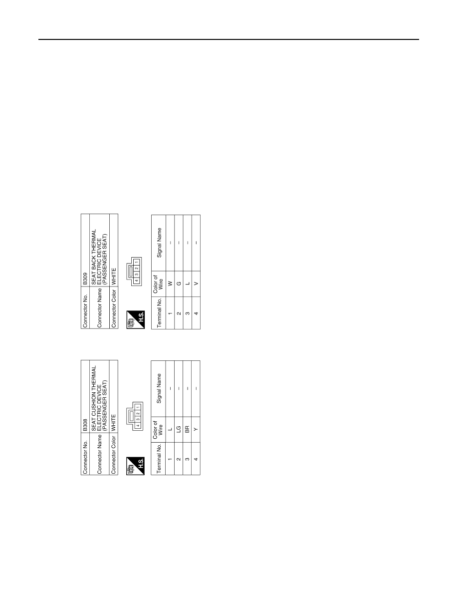
CLIMATE CONTROLLED SEAT SYSTEM
ABJIA0704GB
|
|
|
Content .. 1010 1011 1012 1013 ..
SE-46 < WIRING DIAGRAM > CLIMATE CONTROLLED SEAT SYSTEM ABJIA0704GB |