Murano Cross Cabriolet Z51 (2012 year). Manual - part 67


  Index      Manuals     Murano Cross Cabriolet Z51 (2012 year) - Service and Repair Manual


Search            copyright infringement  


Content      ..     65      66      67      68     ..


Murano Cross Cabriolet Z51 (2012 year). Manual - part 67


PCS

COMPONENT PARTS

PCS-33

< SYSTEM DESCRIPTION >

[POWER DISTRIBUTION SYSTEM]

C

D

E

F

G

H

I

J

K

L

B

A

O

P

N

SYSTEM DESCRIPTION

COMPONENT PARTS

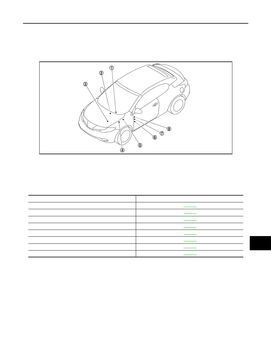
Component Parts Location

INFOID:0000000007563507

Component Description

INFOID:0000000007563508

BCM

INFOID:0000000007563509

BCM controls the various electrical components and simultaneously supplies power according to the power
supply position.
BCM checks the power supply position internally.

IPDM E/R

INFOID:0000000007563510

IPDM E/R detects push-button ignition switch (push switch) status, and transmits push-button ignition switch
status signal (CAN) to BCM.
IPDM E/R receives ignition relay (IPDM E/R) control signal and ignition switch ON signal (CAN) from BCM,
and controls ignition relay (built in IPDM E/R).

JMMIA0877ZZ

1.

BCM

2.

Push-button ignition switch

3.

TCM

4.

IPDM E/R

5.

Stop lamp switch

6.

Ignition relay (fuse block)

7.

Accessory relay

8.

Blower relay

Component

Reference

BCM

PCS-33

IPDM E/R

PCS-33

Ignition relay (IPDM E/R, fuse block)

PCS-34

Accessory relay

PCS-34

Blower relay

PCS-34

Push-button ignition switch

PCS-34

Stop lamp switch

PCS-34

TCM

PCS-34

Revision: 2013 February

2012 Murano CrossCabriolet

PCS-34

< SYSTEM DESCRIPTION >

[POWER DISTRIBUTION SYSTEM]

COMPONENT PARTS

Ignition Relay

INFOID:0000000007563511

BCM turns ON the following relays to supply ignition power supply or ignition switch ON signal to each ECU
when the ignition switch is turned ON.
• Ignition relay (fuse block)
• Ignition relay (IPDM E/R)
BCM compares following status comparing.
• Ignition relay (fuse block) control signal, and power supply position judged by BCM
• Ignition relay (IPDM E/R) control request, and Ignition relay (IPDM E/R) status

Accessory Relay

INFOID:0000000007563512

BCM turns ON the accessory relays to supply accessory power supply or ignition switch ACC signal to each
ECU when the ignition switch is turned ACC or ON.
BCM compares status of accessory relay control signal, and power supply position judged by BCM.

Blower Relay

INFOID:0000000007563513

BCM turns ON the blower relay to supply ignition power supply or ignition switch ON signal to each ECU when
the ignition switch is turned ON.
BCM compares status of blower relay control signal, and power supply position judged by BCM.

Push-Button Ignition Switch

INFOID:0000000007563514

BCM transmits the change in the power supply position with the push-button ignition switch to IPDM E/R via
CAN communication line. IPDM E/R transmits the power supply position status via CAN communication line to
BCM.

Stop Lamp Switch

INFOID:0000000007563515

Stop lamp switch detects that brake pedal is depressed, and then transmits the signal to BCM.

TCM

INFOID:0000000007563516

TCM detects shift position P or N, transmits P/N position signal to BCM.

Revision: 2013 February

2012 Murano CrossCabriolet

PCS

SYSTEM

PCS-35

< SYSTEM DESCRIPTION >

[POWER DISTRIBUTION SYSTEM]

C

D

E

F

G

H

I

J

K

L

B

A

O

P

N

SYSTEM

POWER DISTRIBUTION SYSTEM

POWER DISTRIBUTION SYSTEM : System Description

INFOID:0000000007563517

SYSTEM DESCRIPTION

• PDS (POWER DISTRIBUTION SYSTEM) is the system that BCM controls with the operation of the push-

button ignition switch and performs the power distribution to each power circuit. This system is used instead
of the mechanical power supply changing mechanism with the operation of the conventional key cylinder.

• The push-button ignition switch can be operated when Intelligent Key is in the following condition.
- Intelligent Key is in the detection area of the inside key antenna
- Insert Intelligent Key into the key slot
• The push-button ignition switch operation is input to BCM as a signal. BCM changes the power supply posi-

tion according to the status and operates the following relays to supply power to each power circuit.

- Ignition relay (inside IPDM E/R)
- Ignition relay (inside fuse block)
- Accessory relay
- Blower relay

NOTE:
The push-button ignition switch operation changes due to the conditions of brake pedal, selector lever and
vehicle speed.

• The power supply position can be confirmed with the lighting of the indicators around the push-button igni-

tion switch.

BATTERY SAVER SYSTEM

When all the following conditions are met for 60 minutes, the battery saver system will cut off the power supply
to prevent battery discharge.
• The ignition switch is in the ACC position
• All doors are closed
• Selector lever is in the P position

Reset Condition of Battery Saver System

If any of the following conditions are met the battery saver system is released.
• Opening any door
• Operating with door key cylinder on door lock
• Operating with door request switch on door lock
• Operating with Intelligent Key on door lock
• Press push-button ignition switch and ignition switch will change to ACC position from OFF position.

POWER SUPPLY POSITION CHANGE TABLE BY PUSH-BUTTON IGNITION SWITCH OPERA-
TION

The power supply position changing operation can be performed with the following operations.
NOTE:
• When an Intelligent Key is within the detection area of inside key antenna and when it is inserted to the key

slot, it is equivalent to the operations below.

• When starting the engine, the BCM checks the following conditions and then changes the power supply

position.

- Brake pedal operating condition
- Selector lever position
- Vehicle speed

Vehicle speed: less than 4 km/h (2.5 MPH)

Power supply position

Engine start/stop condition

Push-button ignition switch 

operation frequency

Selector lever

Brake pedal operation condi-

tion

LOCK* 

 ACC

Not depressed

1

LOCK* 

 ACC 

 ON

Not depressed

2

LOCK* 

 ACC 

 ON 

 OFF

Not depressed

3

Revision: 2013 February

2012 Murano CrossCabriolet

PCS-36

< SYSTEM DESCRIPTION >

[POWER DISTRIBUTION SYSTEM]

SYSTEM

NOTE:

*: Power supply position shifts to “LOCK” from “OFF”, when ignition switch is in the OFF position, selector lever is in the P position, and
any of the following conditions are met.

• Closing door

• Opening door

• Door is locked using door request switch

• Door is locked using Intelligent Key

The power supply position shifts to “ACC” when the push-button ignition switch (push switch) is pushed at “LOCK”.

Vehicle speed: 4 km/h (2.5 MPH) or more

Emergency stop operation

• Press and hold the push-button ignition switch for 2 seconds or more.

• Press the push-button ignition switch 3 times or more within 1.5 seconds.

Fail-safe

INFOID:0000000007563518

FAIL-SAFE CONTROL BY DTC

BCM performs fail-safe control when any DTC are detected.

LOCK* 

 START

ACC 

 START

ON 

 START

P or N position

Depressed

1

Engine is running 

 OFF

1

Power supply position

Engine start/stop condition

Push-button ignition switch 

operation frequency

Selector lever

Brake pedal operation condi-

tion

Power supply position

Engine start/stop condition

Push-button ignition switch 

operation frequency

Selector lever

Brake pedal operation condi-

tion

Engine is running 

 ACC 

Emergency stop operation

Engine stall return operation while 
driving 

N position

Not depressed

1

Display contents of CONSULT

Fail-safe

Cancellation

B2190: NATS ANTENNA AMP

Inhibit engine cranking

Erase DTC

B2191: DIFFERENCE OF KEY

Inhibit engine cranking

Erase DTC

B2192: ID DISCORD BCM-ECM

Inhibit engine cranking

Erase DTC

B2193: CHAIN OF BCM-ECM

Inhibit engine cranking

Erase DTC

B2195: ANTI SCANNING

Inhibit engine cranking

Ignition switch ON 

 OFF

B2560: STARTER CONT RELAY

Inhibit engine cranking

500 ms after the following CAN signal communication status be-
comes consistent
• Starter control relay signal
• Starter relay status signal

B2608: STARTER RELAY

Inhibit engine cranking

500 ms after the following signal communication status becomes 
consistent
• Starter motor relay control signal
• Starter relay status signal (CAN)

B260A: IGNITION RELAY

Inhibit engine cranking

500 ms after the following conditions are fulfilled
• IGN relay (IPDM E/R) control signal: OFF (Battery voltage)
• Ignition ON signal (CAN to IPDM E/R): OFF (Request signal)
• Ignition ON signal (CAN from IPDM E/R): OFF (Condition signal)

B260F: ENG STATE SIG LOST

Maintains the power supply 
position attained at the time 
of DTC detection

When any of the following conditions are fulfilled
• Power position changes to ACC
• Receives engine status signal (CAN)

Revision: 2013 February

2012 Murano CrossCabriolet

PCS

SYSTEM

PCS-37

< SYSTEM DESCRIPTION >

[POWER DISTRIBUTION SYSTEM]

C

D

E

F

G

H

I

J

K

L

B

A

O

P

N

B2617: STARTER RELAY CIRC

Inhibit engine cranking

1 second after the starter motor relay control inside BCM becomes 
normal

B2618: BCM

Inhibit engine cranking

1 second after the ignition relay (IPDM E/R) control inside BCM be-
comes normal

B261E: VEHICLE TYPE

Inhibit engine cranking

BCM initialization

Display contents of CONSULT

Fail-safe

Cancellation

Revision: 2013 February

2012 Murano CrossCabriolet

PCS-38

< SYSTEM DESCRIPTION >

[POWER DISTRIBUTION SYSTEM]

DIAGNOSIS SYSTEM (BCM)

DIAGNOSIS SYSTEM (BCM)

COMMON ITEM

COMMON ITEM : CONSULT Function (BCM - COMMON ITEM)

INFOID:0000000007615056

APPLICATION ITEM

CONSULT performs the following functions via CAN communication with BCM.

SYSTEM APPLICATION

BCM can perform the following functions for each system.
NOTE:
It can perform the diagnosis modes except the following for all sub system selection items.

×

: Applicable item

NOTE:

*: This item is displayed, but is not used. 

FREEZE FRAME DATA (FFD)

The BCM records the following vehicle condition at the time a particular DTC is detected, and displays on
CONSULT.

Diagnosis mode

Function Description

Work Support

Changes the setting for each system function.

Self Diagnostic Result

Displays the diagnosis results judged by BCM.

CAN Diag Support Monitor

Monitors the reception status of CAN communication viewed from BCM.

Data Monitor

The BCM input/output signals are displayed.

Active Test

The signals used to activate each device are forcibly supplied from BCM.

Ecu Identification

The BCM part number is displayed.

Configuration

• Read and save the vehicle specification.
• Write the vehicle specification when replacing BCM.

System

Sub system selection item

Diagnosis mode

Work Support

Data Monitor

Active Test

Door lock

DOOR LOCK

×

×

×

Rear window defogger

REAR DEFOGGER

×

×

Warning chime

BUZZER

×

×

Interior room lamp timer

INT LAMP

×

×

×

Exterior lamp

HEAD LAMP

×

×

×

Wiper and washer

WIPER

×

×

×

Turn signal and hazard warning lamps

FLASHER

×

×

×

AIR CONDITONER*

• Intelligent Key system
• Engine start system

INTELLIGENT KEY

×

×

×

Combination switch

COMB SW

×

Body control system

BCM

×

NVIS - NATS

IMMU

×

×

Interior room lamp battery saver

BATTERY SAVER

×

×

×

Trunk lid opener system

TRUNK

×

×

Vehicle security system

THEFT ALM

×

×

×

RAP system

RETAINED PWR

×

Signal buffer system

SIGNAL BUFFER

×

×

TPMS

AIR PRESSURE MONITOR

×

×

×

Revision: 2013 February

2012 Murano CrossCabriolet

PCS

DIAGNOSIS SYSTEM (BCM)

PCS-39

< SYSTEM DESCRIPTION >

[POWER DISTRIBUTION SYSTEM]

C

D

E

F

G

H

I

J

K

L

B

A

O

P

N

NOTE:

*: Power supply position shifts to “LOCK” from “OFF”, when ignition switch is in the OFF position, selector lever is in the P position, and
any of the following conditions are met.

• Closing door

• Opening door

• Door is locked using door request switch

• Door is locked using Intelligent Key

The power supply position shifts to “ACC” when the push-button ignition switch (push switch) is pushed at “LOCK”.

INTELLIGENT KEY

INTELLIGENT KEY : CONSULT Function (BCM - INTELLIGENT KEY)

INFOID:0000000007615052

WORK SUPPORT

CONSULT screen item

Indication/Unit

Description

Vehicle Speed

km/h

Vehicle speed of the moment a particular DTC is detected

Odo/Trip Meter

km

Total mileage (Odometer value) of the moment a particular DTC is detected

Vehicle Condition

SLEEP>LOCK

Power position status of 
the moment a particular 
DTC is detected

While turning BCM status from low power consumption mode to 
normal mode (Power supply position is “LOCK”*)

SLEEP>OFF

While turning BCM status from low power consumption mode to 
normal mode (Power supply position is “OFF”.)

LOCK>ACC

While turning power supply position from “LOCK” to “ACC”

ACC>ON

While turning power supply position from “ACC” to “IGN”

RUN>ACC

While turning power supply position from “RUN” to “ACC” (Vehicle 
is stopping and selector lever is except P position.)

CRANK>RUN

While turning power supply position from “CRANKING” to “RUN” 
(From cranking up the engine to run it)

RUN>URGENT

While turning power supply position from “RUN“ to “ACC” (Emer-
gency stop operation)

ACC>OFF

While turning power supply position from “ACC” to “OFF”

OFF>LOCK

While turning power supply position from “OFF” to “LOCK”*

OFF>ACC

While turning power supply position from “OFF” to “ACC”

ON>CRANK

While turning power supply position from “IGN” to “CRANKING”

OFF>SLEEP

While turning BCM status from normal mode (Power supply posi-
tion is “OFF”.) to low power consumption mode

LOCK>SLEEP

While turning BCM status from normal mode (Power supply posi-
tion is “LOCK”*) to low power consumption mode

LOCK

Power supply position is “LOCK”*

OFF

Power supply position is “OFF” (Ignition switch OFF)

ACC

Power supply position is “ACC” (Ignition switch ACC)

ON

Power supply position is “IGN” (Ignition switch ON with engine 
stopped)

ENGINE RUN

Power supply position is “RUN” (Ignition switch ON with engine 
running)

CRANKING

Power supply position is “CRANKING” (At engine cranking)

IGN Counter

0 - 39

The number of times that ignition switch is turned ON after DTC is detected
• The number is 0 when a malfunction is detected now.
• The number increases like 1 

 2 

 3...38 

 39 after returning to the normal condition 

whenever ignition switch OFF 

 ON.

• The number is fixed to 39 until the self-diagnosis results are erased if it is over 39.

Revision: 2013 February

2012 Murano CrossCabriolet

PCS-40

< SYSTEM DESCRIPTION >

[POWER DISTRIBUTION SYSTEM]

DIAGNOSIS SYSTEM (BCM)

SELF-DIAG RESULT

Refer to 

BCS-54, "DTC Index"

.

DATA MONITOR

Monitor item

Description

CONFIRM KEY FOB ID

It can be checked whether Intelligent Key ID code is registered or not in this mode

AUTO LOCK SET

Auto door lock time can be changed in this mode
• MODE 1: 1 minute
• MODE 2: 5 minutes
• MODE 3: 30 seconds
• MODE 4: 2 minutes

LOCK/UNLOCK BY I-KEY

Door lock/unlock function by door request switch mode can be changed to operate (ON) or not op-
erate (OFF) in this mode

ENGINE START BY I-KEY

Engine start function mode can be changed to operate (ON) or not operate (OFF) with this mode

TRUNK/GLASS HATCH OPEN

Buzzer reminder function mode by trunk lid opener request switch can be changed to operate (ON) 
or not operate (OFF) with this mode

PANIC ALARM SET

Panic alarm button pressing time on Intelligent Key remote control button can be selected from the 
following with this mode
• MODE 1: 0.5 sec.
• MODE 2: Non-operation
• MODE 3: 1.5 sec.

PW DOWN SET

Unlock button pressing time on Intelligent Key button can be selected from the following with this 
mode
• MODE 1: 3 sec.
• MODE 2: Non-operation
• MODE 3: 5 sec.

TAKE OUT FROM WIN WARN

NOTE:
This item is displayed, but cannot be used 

TRUNK OPEN DELAY

Trunk button pressing on Intelligent Key can be selected as per the following in this mode
• MODE 1: Press and hold
• MODE 2: Press twice
• MODE 3: Press and hold, or press twice

LO- BATT OF KEY FOB WARN

Intelligent Key low battery warning mode can be changed to operate (ON) or not operate (OFF) 
with this mode

ANTI KEY LOCK IN FUNCTI

Key reminder function mode can be changed to operate (ON) or not operate (OFF) with this mode.

HAZARD ANSWER BACK

Hazard reminder function mode can be selected from the following with this mode
• LOCK ONLY: Door lock operation only
• UNLOCK ONLY: Door unlock operation only
• LOCK/UNLOCK: Lock/unlock operation
• OFF: Non-operation

ANS BACK I-KEY LOCK

Buzzer reminder function (lock operation) mode by door request switch (driver side and passenger 
side) can be selected from the following with this mode
• Horn chirp: Sound horn
• Buzzer: Sound Intelligent Key warning buzzer
• OFF: Non-operation

ANS BACK I-KEY UNLOCK

Buzzer reminder function (unlock operation) mode by door request switch can be changed to op-
erate (ON) or not operate (OFF) with this mode

SHORT CRANKING OUTPUT

Starter motor can operate during the times below
• 70 msec
• 100  msec
• 200  msec

INSIDE ANT DIAGNOSIS

This function allows inside key antenna self-diagnosis

HORN WITH KEYLESS LOCK

Horn reminder function mode by Intelligent Key button can be changed to operate (ON) or not op-
erate (OFF) with this mode

Revision: 2013 February

2012 Murano CrossCabriolet

PCS

DIAGNOSIS SYSTEM (BCM)

PCS-41

< SYSTEM DESCRIPTION >

[POWER DISTRIBUTION SYSTEM]

C

D

E

F

G

H

I

J

K

L

B

A

O

P

N

Monitor Item

Condition

REQ SW -DR

Indicates [ON/OFF] condition of door request switch (driver side)

REQ SW -AS

Indicates [ON/OFF] condition of door request switch (passenger side)

REQ SW -RR

NOTE:
This item is displayed, but cannot be monitored

REQ SW -RL

NOTE:
This item is displayed, but cannot be monitored

REQ SW -BD/TR

Indicates [ON/OFF] condition of trunk lid opener request switch

PUSH SW

Indicates [ON/OFF] condition of push-button ignition switch

IGN RLY2 -F/B

Indicates [ON/OFF] condition of ignition relay 2

ACC RLY-FB

NOTE:
This item is displayed, but cannot be monitored.

CLUCH SW

NOTE:
This item is displayed, but cannot be monitored

BRAKE SW 1

Indicates [ON/OFF]* condition of brake switch power supply

BRAKE SW 2

Indicates [ON/OFF] condition of brake switch

DETE/CANCL SW

Indicates [ON/OFF] condition of P position

SFT PN/N SW

Indicates [ON/OFF] condition of P or N position

S/L -LOCK

NOTE:
This item is displayed, but cannot be monitored

S/L -UNLOCK

NOTE:
This item is displayed, but cannot be monitored

S/L RELAY -F/B

NOTE:
This item is displayed, but cannot be monitored

UNLK SEN -DR

Indicates [ON/OFF] condition of driver door unlock status

PUSH SW -IPDM

Indicates [ON/OFF] condition of push-button ignition switch

IGN RLY1 -F/B

Indicates [ON/OFF] condition of ignition relay 1

DETE SW -IPDM

Indicates [ON/OFF] condition of P position

SFT PN -IPDM

Indicates [ON/OFF] condition of P or N position

SFT P -MET

Indicates [ON/OFF] condition of P position

SFT N -MET

Indicates [ON/OFF] condition of N position

ENGINE STATE

Indicates [STOP/START/CRANK/RUN] condition of engine states

S/L LOCK-IPDM

NOTE:
This item is displayed, but cannot be monitored

S/L UNLK-IPDM

NOTE:
This item is displayed, but cannot be monitored

S/L RELAY-REQ

NOTE:
This item is displayed, but cannot be monitored

VEH SPEED 1

Display the vehicle speed signal received from combination meter by numerical value [Km/h]

VEH SPEED 2

Display the vehicle speed signal received from ABS or VDC or CVT by numerical value [Km/h]

DOOR STAT-DR

Indicates [LOCK/READY/UNLOCK] condition of driver side door status

DOOR STAT-AS

Indicates [LOCK/READY/UNLOCK] condition of passenger side door status

ID OK FLAG

Indicates [SET/RESET] condition of key ID

PRMT ENG STRT

Indicates [SET/RESET] condition of engine start possibility

PRMT RKE STRT

NOTE:
This item is displayed, but cannot be monitored

KEY SW -SLOT

Indicates [ON/OFF] condition of key slot

TRNK/HAT MNTR

Indicates [ON/OFF] condition of trunk room lamp switch

Revision: 2013 February

2012 Murano CrossCabriolet

PCS-42

< SYSTEM DESCRIPTION >

[POWER DISTRIBUTION SYSTEM]

DIAGNOSIS SYSTEM (BCM)

*: OFF is displayed when brake pedal is depressed while brake switch power supply is OFF.

ACTIVE TEST

RKE-LOCK

Indicates [ON/OFF] condition of door lock signal from Intelligent Key

RKE-UNLOCK

Indicates [ON/OFF] condition of door unlock signal from Intelligent Key

RKE-TR/BD

Indicates [ON/OFF] condition of trunk open signal from Intelligent Key

RKE-PANIC

Indicates [ON/OFF] condition of panic alarm button of Intelligent Key

RKE-P/W OPEN

Indicates [ON/OFF] condition of P/W DOWN signal from Intelligent Key

RKE-MODE CHG

Indicates [ON/OFF] condition of MODE CHANGE signal from Intelligent Key

RKE OPE COUN1

When remote keyless entry receiver (front side) receives the signal transmitted while operating on Intelli-
gent Key, the numerical value start changing.

RKE OPE COUN2

When remote keyless entry receiver (rear side) receives the signal transmitted while operating on Intelli-
gent Key, the numerical value start changing.

Monitor Item

Condition

Test item

Description

BATTERY SAVER

This test is able to check interior room lamp operation.
The interior room lamp will be activated after “ON” on CONSULT screen is touched.

PW REMOTO DOWN SET

This test is able to check power window down operation.
The power window down will be activated after “ON” on CONSULT screen is touched.

INSIDE BUZZER

This test is able to check warning chime in combination meter operation.
• Take away warning chime sounds when “TAKE OUT” on CONSULT screen is touched.
• Key warning chime sounds when “KEY WARN” on CONSULT screen is touched.
• P position warning chime sounds when “P RNG WARN” on CONSULT screen is touched.
• ACC warning chime sounds when “ACC WARN” on CONSULT screen is touched.

OUTSIDE BUZZER

This test is able to check Intelligent Key warning buzzer operation.
The Intelligent Key warning buzzer will be activated after “ON” on CONSULT screen is touched.

INDICATOR

This test is able to check warning lamp operation.
• “KEY” Warning lamp illuminates when “KEY ON” on CONSULT screen is touched.
• “KEY” Warning lamp flashes when “KEY IND” on CONSULT screen is touched.

INT LAMP

This test is able to check interior room lamp operation.
The interior room lamp will be activated after “ON” on CONSULT screen is touched.

LCD

This test is able to check meter display information
• Engine start information displays when “BP N” on CONSULT screen is touched.
• Engine start information displays when “BP I” on CONSULT screen is touched.
• Key ID warning displays when “ID NG” on CONSULT screen is touched.
• ROTAT: This item is displayed, but cannot be tested.
• P position warning displays when SFT P on CONSULT screen is touched.
• Intelligent Key insert information displays when “INSRT” on CONSULT screen is touched.
• Intelligent Key low battery warning displays when “BATT” on CONSULT screen is touched.
• Take away through window warning displays when “NO KY” on CONSULT screen is touched.
• Take away warning display when “OUTKEY” on CONSULT screen is touched.
• OFF position warning display when “LK WN” on CONSULT screen is touched.

TRUNK/GLASS HATCH

NOTE:
This item is displayed, but cannot be tested.

FLASHER

This test is able to check hazard warning lamp operation.
The hazard warning lamps will be activated after “ON” on CONSULT screen is touched.

HORN

This test is able to check horn operation.
The horn will be activated after “ON” on CONSULT screen is touched.

P RANGE

This test is able to check CVT shift selector power supply
CVT shift selector power is supplied when “ON” on CONSULT screen is touched.

ENGINE SW ILLUMI

This test is able to check push-ignition switch illumination operation.
Push-ignition switch illumination illuminates when “ON” on CONSULT screen is touched.

LOCK INDICATOR

This test is able to check indicator in push-ignition switch operation.
Indicator in push-button ignition switch illuminates when “ON” on CONSULT screen is touched.

Revision: 2013 February

2012 Murano CrossCabriolet

PCS

DIAGNOSIS SYSTEM (BCM)

PCS-43

< SYSTEM DESCRIPTION >

[POWER DISTRIBUTION SYSTEM]

C

D

E

F

G

H

I

J

K

L

B

A

O

P

N

ACC INDICATOR

This test is able to check indicator in push-ignition switch operation.
Indicator in push-button ignition switch illuminates when “ON” on CONSULT screen is touched.

IGNITION ON IND

This test is able to check indicator in push-ignition switch operation.
Indicator in push-button ignition switch illuminates when “ON” on CONSULT screen is touched.

KEY SLOT ILLUMI

This test is able to check key slot illumination operation.
Key slot illumination flash when “ON” on CONSULT screen is touched.

TRUNK/BACK DOOR

NOTE:
This item is displayed, but cannot be tested.

Test item

Description

Revision: 2013 February

2012 Murano CrossCabriolet

PCS-44

< ECU DIAGNOSIS INFORMATION >

[POWER DISTRIBUTION SYSTEM]

BCM, IPDM E/R

ECU DIAGNOSIS INFORMATION

BCM, IPDM E/R

List of ECU Reference

INFOID:0000000007563521

ECU

Reference

BCM

BCS-31, "Reference Value"

BCS-53, "Fail-safe"

BCS-53, "DTC Inspection Priority Chart"

BCS-54, "DTC Index"

IPDM E/R

PCS-15, "Reference Value"

PCS-21, "Fail-safe"

PCS-23, "DTC Index"

Revision: 2013 February

2012 Murano CrossCabriolet

PCS

POWER DISTRIBUTION SYSTEM

PCS-45

< WIRING DIAGRAM >

[POWER DISTRIBUTION SYSTEM]

C

D

E

F

G

H

I

J

K

L

B

A

O

P

N

WIRING DIAGRAM

POWER DISTRIBUTION SYSTEM

Wiring Diagram - PDS (POWER DISTRIBUTION SYSTEM) -

INFOID:0000000007563522

For connector terminal arrangements, harness layouts, and alphabets in a 

 (option abbreviation; if not

described in wiring diagram), refer to 

GI-12, "Connector Information"

.

JCMWA8066GB

Revision: 2013 February

2012 Murano CrossCabriolet

PCS-46

< WIRING DIAGRAM >

[POWER DISTRIBUTION SYSTEM]

POWER DISTRIBUTION SYSTEM

JCMWA8067GB

Revision: 2013 February

2012 Murano CrossCabriolet

PCS

DIAGNOSIS AND REPAIR WORK FLOW

PCS-47

< BASIC INSPECTION >

[POWER DISTRIBUTION SYSTEM]

C

D

E

F

G

H

I

J

K

L

B

A

O

P

N

BASIC INSPECTION

DIAGNOSIS AND REPAIR WORK FLOW

Work Flow

INFOID:0000000007615060

OVERALL SEQUENCE

DETAILED FLOW

JMKIA8652GB

Revision: 2013 February

2012 Murano CrossCabriolet

PCS-48

< BASIC INSPECTION >

[POWER DISTRIBUTION SYSTEM]

DIAGNOSIS AND REPAIR WORK FLOW

1.

GET INFORMATION FOR SYMPTOM

1.

Get detailed information from the customer about the symptom (the condition and the environment when
the incident/malfunction occurs).

2.

Check operation condition of the function that is malfunctioning.

>> GO TO 2.

2.

CHECK DTC

1.

Check DTC.

2.

Perform the following procedure if DTC is detected.

-

Record DTC and freeze frame data (Print them out using CONSULT.)

-

Erase DTC.

-

Study the relationship between the cause detected by DTC and the symptom described by the customer.

3.

Check related service bulletins for information.

Are any symptoms described and any DTC detected?

Symptom is described, DTC is detected>>GO TO 3.
Symptom is described, DTC is not detected>>GO TO 4.
Symptom is not described, DTC is detected>>GO TO 5.

3.

CONFIRM THE SYMPTOM

Try to confirm the symptom described by the customer.
Also study the normal operation and fail-safe related to the symptom.
Verify relation between the symptom and the condition when the symptom is detected.

>> GO TO 5.

4.

CONFIRM THE SYMPTOM

Try to confirm the symptom described by the customer.
Verify relation between the symptom and the condition when the symptom is detected.

>> GO TO 6.

5.

PERFORM DTC CONFIRMATION PROCEDURE

Perform DTC CONFIRMATION PROCEDURE for the detected DTC, and then check that DTC is detected
again. At this time, always connect CONSULT to the vehicle, and check self diagnostic results in real time.
If two or more DTCs are detected, refer to 

BCS-53, "DTC Inspection Priority Chart"

, and determine trouble

diagnosis order.
NOTE:
• Freeze frame data is useful if the DTC is not detected.
• Perform Component Function Check if DTC CONFIRMATION PROCEDURE is not included on Service

Manual. This simplified check procedure is an effective alternative though DTC cannot be detected during
this check.
If the result of Component Function Check is NG, it is the same as the detection of DTC by DTC CONFIR-
MATION PROCEDURE.

Is DTC detected?

YES

>> GO TO 7.

NO

>> Check according to 

GI-40, "Intermittent Incident"

.

6.

DETECT MALFUNCTIONING SYSTEM BY SYMPTOM DIAGNOSIS

Detect malfunctioning system according to SYMPTOM DIAGNOSIS based on the confirmed symptom in step
4, and determine the trouble diagnosis order based on possible causes and symptom.

Is the symptom described?

YES

>> GO TO 7.

NO

>> Monitor input data from related sensors or check voltage of related module terminals using CON-

SULT.

7.

DETECT MALFUNCTIONING PART BY DIAGNOSIS PROCEDURE

Revision: 2013 February

2012 Murano CrossCabriolet


Content      ..     65      66      67      68     ..