Nissan Murano Z51 (2012 year). Manual - part 28


  Index      Manuals     Nissan Murano Z51 (2012 year) - Service and Repair Manual


Search            copyright infringement  


Content      ..     26      27      28      29     ..


Nissan Murano Z51 (2012 year). Manual - part 28


FRONT DRIVE SHAFT

FAX-27

< REMOVAL AND INSTALLATION >

[2WD]

C

E

F

G

H

I

J

K

L

M

A

B

FAX

N

O

P

b.

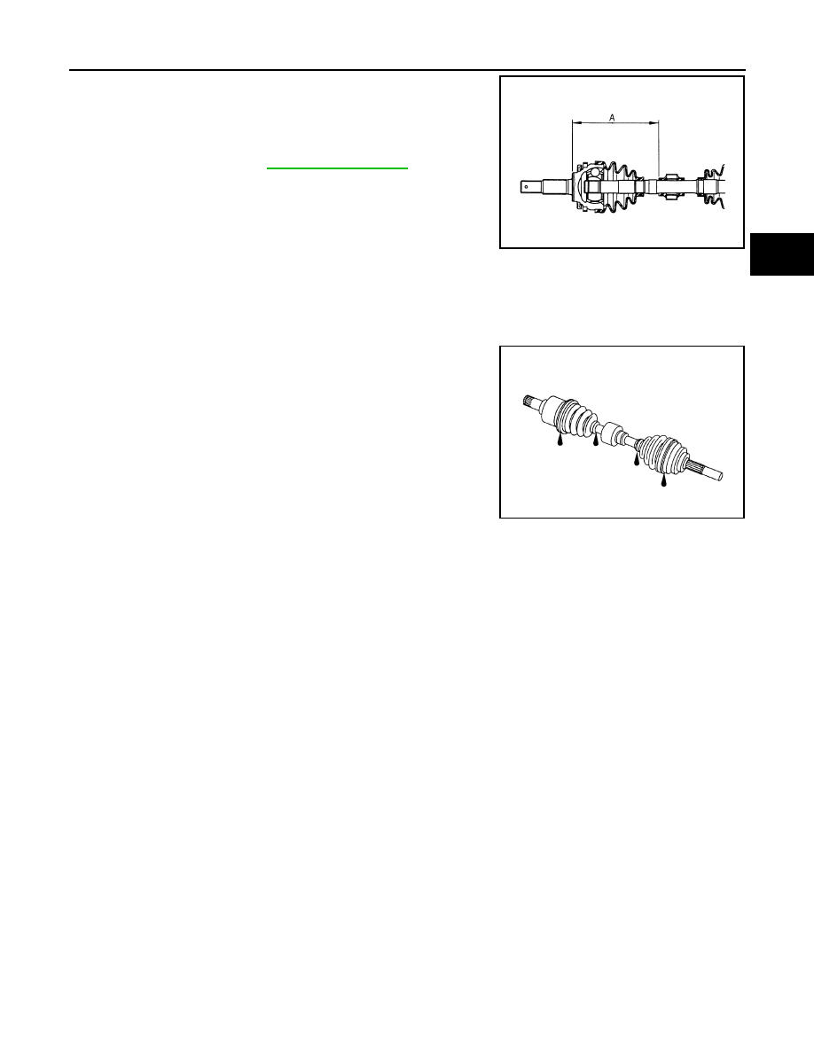
Secure dynamic damper with bands in the following specified
position (A) when installing.

CAUTION:

Never reuse bands.

Inspection

INFOID:0000000007541208

INSPECTION AFTER REMOVAL

• Move joint up/down, left/right, and in the axial directions. Check for motion that is not smooth and for signifi-

cant looseness.

• Check boot for cracks, damage, and leakage of grease.
• Disassemble drive shaft and exchange malfunctioning part if there

is a non-standard condition.

INSPECTION AFTER DISASSEMBLY

Shaft

Check shaft for runout, cracks, or other damage. Replace if necessary.

Dynamic Damper

Check damper for cracks or wear. Replace if necessary.

Joint Sub-Assembly (Wheel Side)

Check the following:
• Joint sub-assembly for rough rotation and excessive axial looseness.
• The inside of the joint sub-assembly for entry of foreign material.
• Joint sub-assembly for compression scars, cracks, and fractures inside of joint sub-assembly.
Replace joint sub-assembly if there are any non-standard conditions of components.

Housing Assembly (Transaxle Side)

Replace housing assembly if there is scratching or wear of housing assembly roller contact surface.

Support Bearing (Right Side)

Make sure wheel bearing rolls freely and is free from noise, cracks, pitting or wear. Replace support bearing if
there are any non-standard conditions.

Support Bearing Bracket (Right Side)

Check for bending, cracks, or damage. Replace support bearing bracket if there are any non-standard condi-
tions.

A : 

Refer 

to 

FAX-28, "Drive Shaft"

.

JPDIF0178ZZ

SDIA1190J

Revision: 2013 February

2012 MURANO

FAX-28

< SERVICE DATA AND SPECIFICATIONS (SDS) 

[2WD]

SERVICE DATA AND SPECIFICATIONS (SDS)

SERVICE DATA AND SPECIFICATIONS (SDS)

SERVICE DATA AND SPECIFICATIONS (SDS)

Wheel Bearing

INFOID:0000000007541209

Drive Shaft

INFOID:0000000007541210

Item

Standard

Axial end play

0.05 mm (0.002 in) or less

Item

Standard

Left side

Right side

Grease quantity

Wheel side

170 – 190 g (6.00 – 6.70 oz)

Transaxle side

155 – 175 g (5.47 – 6.17 oz)

Boots installed length

Wheel side

158.6 mm (6.24 in)

Transaxle side

163.67 mm (6.44 in)

Dimension of dynamic damper

202 – 208 mm (7.95 – 8.19 in)

Revision: 2013 February

2012 MURANO

NOISE, VIBRATION AND HARSHNESS (NVH) TROUBLESHOOTING

FAX-29

< SYMPTOM DIAGNOSIS >

[AWD]

C

E

F

G

H

I

J

K

L

M

A

B

FAX

N

O

P

SYMPTOM DIAGNOSIS

NOISE, VIBRATION AND HARSHNESS (NVH) TROUBLESHOOTING

NVH Troubleshooting Chart

INFOID:0000000007541211

Use chart below to find the cause of the symptom. If necessary, repair or replace these parts.

×

: Applicable

Reference

F

AX-52

F

AX-36

F

AX-34

NV

H in

 F

A

X

 an

FSU s

e

c

tio

ns

Re

fe

r to

 FRONT AXL

E i

n

 t

h

is cha

rt

NVH in WT 

section

NVH in WT 

section

Ref

e

r t

o

 DRIVE

 SHAFT

 in this 

chart

NVH in BR 

section

NVH in S

T

 section

Possible cause and SUSPECTED PARTS

Ex

ce

ss

iv

e joi

nt an

gl

e

Jo

in

t sl

id

in

g

 re

si

st

a

n

c

e

Im

ba

la

nc

e

Imp

rop

er i

ns

ta

lla

ti

o

n,

 lo

os

en

es

s

Part

s interf

erence

Whe

e

l be

ari

n

g

 da

ma

ge

FRONT A

X

LE 

AND FRONT SUSP

ENSION

FRONT A

XLE

TI

RE

ROAD WHEE

L

DRIVE SHAFT

BRAKE

STE

E

RING

Symptom

DRIVE 
SHAFT

Noise

×

×

×

×

×

×

×

×

×

Shake

×

×

×

×

×

×

×

×

×

FRONT 
AXLE

Noise

×

×

×

×

×

×

×

×

×

Shake

×

×

×

×

×

×

×

×

×

Vibration

×

×

×

×

×

×

×

Shimmy

×

×

×

×

×

×

×

Judder

×

×

×

×

×

×

Poor quality ride or handling

×

×

×

×

×

Revision: 2013 February

2012 MURANO

FAX-30

< PRECAUTION >

[AWD]

PRECAUTIONS

PRECAUTION

PRECAUTIONS

FOR USA AND CANADA

FOR USA AND CANADA : Precaution for Supplemental Restraint System (SRS) "AIR 
BAG" and "SEAT BELT PRE-TENSIONER"

INFOID:0000000007541212

The Supplemental Restraint System such as “AIR BAG” and “SEAT BELT PRE-TENSIONER”, used along
with a front seat belt, helps to reduce the risk or severity of injury to the driver and front passenger for certain
types of collision. This system includes seat belt switch inputs and dual stage front air bag modules. The SRS
system uses the seat belt switches to determine the front air bag deployment, and may only deploy one front
air bag, depending on the severity of a collision and whether the front occupants are belted or unbelted.
Information necessary to service the system safely is included in the “SRS AIR BAG” and “SEAT BELT” of this
Service Manual.

WARNING:

Always observe the following items for preventing accidental activation.
• To avoid rendering the SRS inoperative, which could increase the risk of personal injury or death in

the event of a collision that would result in air bag inflation, all maintenance must be performed by
an authorized NISSAN/INFINITI dealer.

• Improper maintenance, including incorrect removal and installation of the SRS, can lead to personal

injury caused by unintentional activation of the system. For removal of Spiral Cable and Air Bag
Module, see “SRS AIR BAG”.

• Never use electrical test equipment on any circuit related to the SRS unless instructed to in this Ser-

vice Manual. SRS wiring harnesses can be identified by yellow and/or orange harnesses or harness
connectors.

PRECAUTIONS WHEN USING POWER TOOLS (AIR OR ELECTRIC) AND HAMMERS

WARNING:

Always observe the following items for preventing accidental activation.
• When working near the Air Bag Diagnosis Sensor Unit or other Air Bag System sensors with the

ignition ON or engine running, never use air or electric power tools or strike near the sensor(s) with
a hammer. Heavy vibration could activate the sensor(s) and deploy the air bag(s), possibly causing
serious injury.

• When using air or electric power tools or hammers, always switch the ignition OFF, disconnect the

battery, and wait at least 3 minutes before performing any service.

FOR USA AND CANADA : Precautions for Drive Shaft

INFOID:0000000007541213

• Observe the following precautions when disassembling and assembling drive shaft.
• Never disassemble joint sub-assembly because it is non-overhaul parts.
• Perform work in a location which is as dust-free as possible.
• Clean the parts, before disassembling and assembling.
• Prevent the entry of foreign objects during disassembly of the service location.
• Reassemble disassembled parts carefully in the correct order. If work is interrupted, a clean cover must be

placed over parts.

• Use paper waste. Fabric shop cloths must not be used because of the danger of lint adhering to parts.
• Clean disassembled parts (except for rubber parts) with kerosene which shall be removed by blowing with

air or wiping with paper waste.

FOR MEXICO

FOR MEXICO : Precaution for Supplemental Restraint System (SRS) "AIR BAG" and 
"SEAT BELT PRE-TENSIONER"

INFOID:0000000007541214

The Supplemental Restraint System such as “AIR BAG” and “SEAT BELT PRE-TENSIONER”, used along
with a front seat belt, helps to reduce the risk or severity of injury to the driver and front passenger for certain
types of collision. Information necessary to service the system safely is included in the “SRS AIR BAG” and
“SEAT BELT” of this Service Manual.

WARNING:

Revision: 2013 February

2012 MURANO

PRECAUTIONS

FAX-31

< PRECAUTION >

[AWD]

C

E

F

G

H

I

J

K

L

M

A

B

FAX

N

O

P

Always observe the following items for preventing accidental activation.
• To avoid rendering the SRS inoperative, which could increase the risk of personal injury or death in

the event of a collision that would result in air bag inflation, all maintenance must be performed by
an authorized NISSAN/INFINITI dealer.

• Improper maintenance, including incorrect removal and installation of the SRS, can lead to personal

injury caused by unintentional activation of the system. For removal of Spiral Cable and Air Bag
Module, see “SRS AIR BAG”.

• Never use electrical test equipment on any circuit related to the SRS unless instructed to in this Ser-

vice Manual. SRS wiring harnesses can be identified by yellow and/or orange harnesses or harness
connectors.

PRECAUTIONS WHEN USING POWER TOOLS (AIR OR ELECTRIC) AND HAMMERS

WARNING:

Always observe the following items for preventing accidental activation.
• When working near the Air Bag Diagnosis Sensor Unit or other Air Bag System sensors with the

ignition ON or engine running, never use air or electric power tools or strike near the sensor(s) with
a hammer. Heavy vibration could activate the sensor(s) and deploy the air bag(s), possibly causing
serious injury.

• When using air or electric power tools or hammers, always switch the ignition OFF, disconnect the

battery, and wait at least 3 minutes before performing any service.

FOR MEXICO : Precautions for Drive Shaft

INFOID:0000000007541215

• Observe the following precautions when disassembling and assembling drive shaft.
• Never disassemble joint sub-assembly because it is non-overhaul parts.
• Perform work in a location which is as dust-free as possible.
• Clean the parts, before disassembling and assembling.
• Prevent the entry of foreign objects during disassembly of the service location.
• Reassemble disassembled parts carefully in the correct order. If work is interrupted, a clean cover must be

placed over parts.

• Use paper waste. Fabric shop cloths must not be used because of the danger of lint adhering to parts.
• Clean disassembled parts (except for rubber parts) with kerosene which shall be removed by blowing with

air or wiping with paper waste.

Revision: 2013 February

2012 MURANO

FAX-32

< PREPARATION >

[AWD]

PREPARATION

PREPARATION

PREPARATION

Special Service Tool

INFOID:0000000007541216

The actual shapes of Kent-More tools may differ from those of special service tools illustrated here.

Tool number 
(Kent-More No.)
Tool name

Description

KV40107300
(

)

Boot band crimping tool

Installing boot band

KV40107500
(

)

Drive shaft attachment

Removing drive shaft

KV38107900
(

)

Protector
a: 32 mm (1.26 in) dia.

Installing drive shaft

ST35271000
(

)

Drift
a: 72 mm (2.83 in) dia.
b: 63 mm (2.48 in) dia.

• Installing oil seal
• Installing support bearing

ST17130000
(

)

Drift
a: 32 mm (1.26 in) dia.
b: 60 mm (2.36 in) dia.

Removing support bearing

ZZA1229D

ZZA1230D

PDIA1183J

ZZA0701D

ZZA0836D

Revision: 2013 February

2012 MURANO

PREPARATION

FAX-33

< PREPARATION >

[AWD]

C

E

F

G

H

I

J

K

L

M

A

B

FAX

N

O

P

Commercial Service Tool

INFOID:0000000007541217

Tool name

Description

Power tool

Loosening bolts and nuts

PBIC0190E

Revision: 2013 February

2012 MURANO

FAX-34

< PERIODIC MAINTENANCE >

[AWD]

FRONT WHEEL HUB AND KNUCKLE

PERIODIC MAINTENANCE

FRONT WHEEL HUB AND KNUCKLE

Inspection

INFOID:0000000007541218

MOUNTING INSPECTION

Make sure that the mounting conditions (looseness, backlash) of each component and component conditions
(wear, damage) are normal.

WHEEL BEARING INSPECTION

• Move wheel hub and bearing assembly in the axial direction by hand. Make sure there is no looseness of

wheel bearing.

• Rotate wheel hub and bearing assembly and make sure there is no unusual noise or other irregular condi-

tions. If there is any of irregular conditions, replace wheel hub and bearing assembly.

Standard

Axial end play

: Refer to 

FAX-53, "Wheel Bearing"

.

Revision: 2013 February

2012 MURANO

FRONT DRIVE SHAFT

FAX-35

< PERIODIC MAINTENANCE >

[AWD]

C

E

F

G

H

I

J

K

L

M

A

B

FAX

N

O

P

FRONT DRIVE SHAFT

Inspection

INFOID:0000000007541219

• Check drive shaft mounting point and joint for looseness and other damage.
• Check boot for cracks and other damage.

CAUTION:

Replace entire drive shaft assembly when noise or vibration occurs from drive shaft.

Revision: 2013 February

2012 MURANO

FAX-36

< REMOVAL AND INSTALLATION >

[AWD]

FRONT WHEEL HUB AND KNUCKLE

REMOVAL AND INSTALLATION

FRONT WHEEL HUB AND KNUCKLE

Exploded View

INFOID:0000000007541220

Removal and Installation

INFOID:0000000007541221

REMOVAL

1.

Remove tires with power tool.

2.

Remove wheel sensor and sensor harness. Refer to 

BRC-121, "FRONT WHEEL SENSOR : Exploded

View"

.

3.

Remove lock plate from strut assembly. Refer to 

BR-21, "FRONT : Exploded View"

.

4.

Remove caliper assembly. Hang caliper assembly not to interfere with work. Refer to 

BR-37, "BRAKE

CALIPER ASSEMBLY (1 PISTON TYPE) : Exploded View"

.

CAUTION:

Never depress brake pedal while brake caliper is removed.

5.

Remove disc rotor. Refer to 

BR-38, "BRAKE CALIPER ASSEMBLY (1 PISTON TYPE) : Removal and

Installation"

.

6.

Remove cotter pin, and then loosen wheel hub lock nut with power tool.

7.

Patch wheel hub lock nut with a piece of wood. Hammer the wood to disengage wheel hub and bearing
assembly from drive shaft.

CAUTION:

• Never place drive shaft joint at an extreme angle. Also be careful not to overextend slide joint.
• Never allow drive shaft to hang down without support for joint sub-assembly, shaft and the other

parts.

NOTE:
Use suitable puller, if wheel hub and bearing assembly and drive shaft cannot be separated even after
performing the above procedure.

8.

Remove wheel hub lock nut.

9.

Remove strut assembly from steering knuckle. Refer to 

FSU-9, "Exploded View"

.

10. Remove drive shaft from wheel hub and bearing assembly, suspend the drive shaft with suitable wire.

Refer to 

FAX-43, "Exploded View"

.

1.

Steering knuckle

2.

Splash guard

3.

Wheel hub and bearing assembly

4.

Wheel hub lock nut

5.

Cotter pin

Refer to 

GI-4, "Components"

 for symbols in the figure.

JPDIF0274GB

Revision: 2013 February

2012 MURANO

FRONT WHEEL HUB AND KNUCKLE

FAX-37

< REMOVAL AND INSTALLATION >

[AWD]

C

E

F

G

H

I

J

K

L

M

A

B

FAX

N

O

P

11. Temporarily tighten strut assembly and steering knuckle.

12. Remove wheel hub and bearing assembly, and then remove splash guard.
13. Remove steering outer socket from steering knuckle. Refer to 

ST-44, "Exploded View"

.

14. Remove steering knuckle from transverse link.

15. Remove steering knuckle from steering knuckle.

INSTALLATION

Note the following, and install in the reverse order of the removal.
• Clean the matching surface of wheel hub lock nut and wheel hub and bearing assembly.

CAUTION:

Never apply lubricating oil to these matching surface.

• Clean the matching surface of drive shaft and wheel hub and bearing assembly.

CAUTION:

Apply paste [service parts (440037S000)] to cover entire flat
surface (A) of joint sub-assembly of drive shaft.

• Never use a power tool to tighten the wheel hub lock nut.
• Perform the final tightening of each of parts under unladen condi-

tions, which were removed when removing wheel hub and bearing
assembly and axle housing. 

• Never reuse cotter pin.

Inspection

INFOID:0000000007541222

INSPECTION AFTER REMOVAL

Check components for deformation, cracks, and other damage. Replace if necessary.

Ball Joint Inspection

Check boots of transverse link and steering outer socket ball joint for breakage, axial play, and torque. Refer to

FSU-11, "Inspection"

 and 

ST-54, "Inspection"

.

INSPECTION AFTER INSTALLATION

1.

Check wheel sensor harness for proper connection. Refer to 

BRC-121, "FRONT WHEEL SENSOR :

Exploded View"

.

2.

Check the wheel alignment. Refer to 

FSU-7, "Inspection"

.

3.

Adjust neutral position of steering angle sensor. Refer to 

BRC-9, "ADJUSTMENT OF STEERING ANGLE

SENSOR NEUTRAL POSITION : Special Repair Requirement"

.

Amount paste

: 1.0 – 3.0 g (0.04 – 0.10 oz)

JPDIG0122ZZ

Revision: 2013 February

2012 MURANO

FAX-38

< REMOVAL AND INSTALLATION >

[AWD]

FRONT DRIVE SHAFT BOOT

FRONT DRIVE SHAFT BOOT

Exploded View

INFOID:0000000007541223

LEFT SIDE

RIGHT SIDE

1.

Circular clip

2.

Dust shield

3.

Housing assembly

4.

Boot band

5.

Boot

6.

Circular clip

7.

Joint sub-assembly 

: Wheel side

1: Fill NISSAN Genuine grease or equivalent.

2: Apply paste [service parts (440037S000)].

Refer to 

GI-4, "Components"

 for symbols not described on the above.

JPDIF0243ZZ

1.

Joint sub-assembly

2.

Circular clip

3.

Boot band

4.

Boot

5.

Damper band

6.

Dynamic damper

7.

Housing assembly

8.

Circular clip

9.

Dust shield

10. Oil seal

11.

Bearing housing

12. Bearing bracket

JPDIF0241GB

Revision: 2013 February

2012 MURANO

FRONT DRIVE SHAFT BOOT

FAX-39

< REMOVAL AND INSTALLATION >

[AWD]

C

E

F

G

H

I

J

K

L

M

A

B

FAX

N

O

P

WHEEL SIDE

WHEEL SIDE : Removal and Installation

INFOID:0000000007541224

REMOVAL

1.

Remove tires with power tool.

2.

Remove wheel sensor and sensor harness. Refer to 

BRC-121, "FRONT WHEEL SENSOR : Exploded

View"

.

3.

Remove lock plate from strut assembly. Refer to 

BR-21, "FRONT : Exploded View"

.

4.

Remove caliper assembly. Hang caliper assembly not to interfere with work. Refer to 

BR-37, "BRAKE

CALIPER ASSEMBLY (1 PISTON TYPE) : Exploded View"

.

CAUTION:

Never depress brake pedal while brake caliper is removed.

5.

Remove disc rotor. Refer to 

BR-38, "BRAKE CALIPER ASSEMBLY (1 PISTON TYPE) : Removal and

Installation"

.

6.

Remove cotter pin, and then loosen wheel hub lock nut with power tool. Refer to 

FAX-36, "Exploded

View"

.

7.

Patch wheel hub lock nut with a piece of wood. Hammer the wood to disengage wheel hub and bearing
assembly from drive shaft.

CAUTION:

• Never place drive shaft joint at an extreme angle. Also be careful not to overextend slide joint.
• Never allow drive shaft to hang down without support for joint sub-assembly, housing assembly

and the other parts.

NOTE:
Use suitable puller, if wheel hub and bearing assembly and drive shaft cannot be separated even after
performing the above procedure.

8.

Remove wheel hub lock nut.

9.

Remove strut assembly from steering knuckle. Refer to 

FSU-9, "Exploded View"

.

10. Remove drive shaft from wheel hub and bearing assembly.
11. Remove boot bands, and then remove boot from joint sub-assembly.

12. Screw drive shaft puller (A) into joint sub-assembly screw part to

a length of 30 mm (1.18 in) or more. Support drive shaft with one
hand and pull out joint sub-assembly with a sliding hammer (B)
from housing assembly.

CAUTION:

• Align a sliding hammer and drive shaft and remove them

by pulling firmly and uniformly.

• If joint sub-assembly cannot be pulled out, try after

removing drive shaft from vehicle.

13. Snap ling

14. Dust shield

15. collor

16. Link shaft

17. Support bearing bracket

A:

Oil seal lip

: Wheel side

1: Fill NISSAN Genuine grease or equivalent.

2: Apply paste [service parts (440037S000)].

3: Appy multi - purpose grease.

Refer to 

GI-4, "Components"

 for symbols not described on the above.

JPDIF0022ZZ

Revision: 2013 February

2012 MURANO

FAX-40

< REMOVAL AND INSTALLATION >

[AWD]

FRONT DRIVE SHAFT BOOT

13. Remove circular clip (1) from housing assembly.

14. Remove boot from housing assembly.

INSTALLATION

1.

Clean the old grease on joint sub-assembly with paper waste.

2.

Fill serration slot joint sub-assembly with NISSAN genuine grease or equivalent until the serration slot and
ball groove become full to the brim.

CAUTION:

After applying grease, use a paper waste to wipe off old grease that has oozed out.

3.

Install boot and boot bands to housing assembly.

CAUTION:

• Wrap serration on housing assembly with tape to protect the boot from damage.
• Never reuse boot and boot band.

4.

Remove the tape wrapped around the serration on housing assembly.

5.

Position the circular clip on groove at the housing assembly edge.

CAUTION:

Never reuse circular clip.
NOTE:
Drive joint inserter is recommended when installing circular clip.

6.

Align both center axles of the housing assembly edge and joint sub-assembly. Then assemble housing
assembly with joint sub-assembly holding circular clip.

7.

Install joint sub-assembly (1) to housing assembly using plastic
hammer.

CAUTION:

Confirm that joint sub-assembly is correctly engaged while
rotating drive housing assembly.

8.

Apply the specified amount of grease into the boot inside from
large diameter side of boot.

9.

Install the boot securely into grooves (indicated by “*” marks)
shown in the figure.

CAUTION:

If grease adheres to the boot mounting surface (indicated
by “*” mark) on the housing assembly or joint sub-assem-
bly, boot may be removed. Remove all grease from the boot
mounting surface.

10. To prevent the deformation of the boot, adjust the boot installa-

tion length (L) to the specified value shown below by inserting
the suitable tool into inside of the boot from the large diameter
side of the boot and discharging the inside air.

CAUTION:

• If the boot mounting length exceeds the standard, it may cause breakage of boot.

JPDIF0007ZZ

Grease amount

: Refer to 

FAX-53, "Drive Shaft"

.

JPDIF0011ZZ

L

: Refer to 

FAX-53, "Drive Shaft"

.

JPDIF0222ZZ

Revision: 2013 February

2012 MURANO

FRONT DRIVE SHAFT BOOT

FAX-41

< REMOVAL AND INSTALLATION >

[AWD]

C

E

F

G

H

I

J

K

L

M

A

B

FAX

N

O

P

• Be careful not to touch the inside of the boot with a tip of tool.

11. Secure the large and small ends of the boot with boot bands

using the boot band crimping tool (A) [SST: KV40107300 (

)].

CAUTION:

Never reuse boot band.

NOTE:
Secure boot band so that dimension (A) meets the specification
as shown in the figure.

12. Secure joint sub-assembly and housing assembly, and then

make sure that they are in the correct position when rotating
boot. Reinstall them using boot bands when boot installation
positions become incorrect.

CAUTION:

Never reuse boot band.

13. Clean the matching surface of wheel hub lock nut and wheel

hub and bearing assembly.

CAUTION:

Never apply lubricating oil to these matching surface.

14. Clean the matching surface of drive shaft and wheel hub and bearing assembly.

CAUTION:

Apply paste [service parts (440037S000)] to cover entire flat
surface (A) of joint sub-assembly of drive shaft.

15. Insert drive shaft to wheel hub and bearing assembly, and then temporarily tighten wheel hub lock nut.

16. Install strut assembly to steering knuckle. Refer to 

FSU-9, "Exploded View"

.

17. Install disc rotor. Refer to 

BR-38, "BRAKE CALIPER ASSEMBLY (1 PISTON TYPE) : Removal and Instal-

lation"

.

18. Install caliper assembly to steering knuckle. Refer to 

BR-37, "BRAKE CALIPER ASSEMBLY (1 PISTON

TYPE) : Exploded View"

.

19. Install lock plate to strut assembly. Refer to 

BR-21, "FRONT : Exploded View"

.

20. Install wheel sensor and sensor harness to steering knuckle. Refer to 

BRC-121, "FRONT WHEEL SEN-

SOR : Exploded View"

.

21. Tighten the wheel hub lock nut to the specified torque. Refer to 

FAX-36, "Exploded View"

.

NOTE:
• Never use a power tool to tighten the wheel hub lock nut.
• Perform the final tightening of each of parts under unladen conditions, which were removed when

removing wheel hub and bearing assembly and axle housing. 

22. Install cotter pin. Refer to 

FAX-36, "Exploded View"

.

JPDIF0012ZZ

A

: 7.0 mm (0.276 in) or less

Amount paste

: 1.0 – 3.0 g (0.04 – 0.10 oz)

JPDIF0268ZZ

JPDIG0122ZZ

Revision: 2013 February

2012 MURANO

FAX-42

< REMOVAL AND INSTALLATION >

[AWD]

FRONT DRIVE SHAFT BOOT

CAUTION:

• Never reuse cotter pin.
• Bend cotter pin at the root sufficiently to prevent any looseness.

TRANSAXLE SIDE

TRANSAXLE SIDE : Removal and Installation

INFOID:0000000007541225

NOTE:
Remove boot after removing drive shaft. Refer to 

FAX-44, "LEFT SIDE : Removal and Installation"

 (left side),

FAX-45, "RIGHT SIDE : Removal and Installation"

 (right side).

Inspection

INFOID:0000000007541226

INSPECTION AFTER REMOVAL

• Move joint up/down, left/right, and in the axial directions. Check for motion that is not smooth and for signifi-

cant looseness.

• Check boot for cracks, damage, and leakage of grease.
• Disassemble drive shaft and exchange malfunctioning part if there

is a non-standard condition.

SDIA1190J

Revision: 2013 February

2012 MURANO


Content      ..     26      27      28      29     ..