Nissan Murano Z50 (2007 year). Manual - part 74
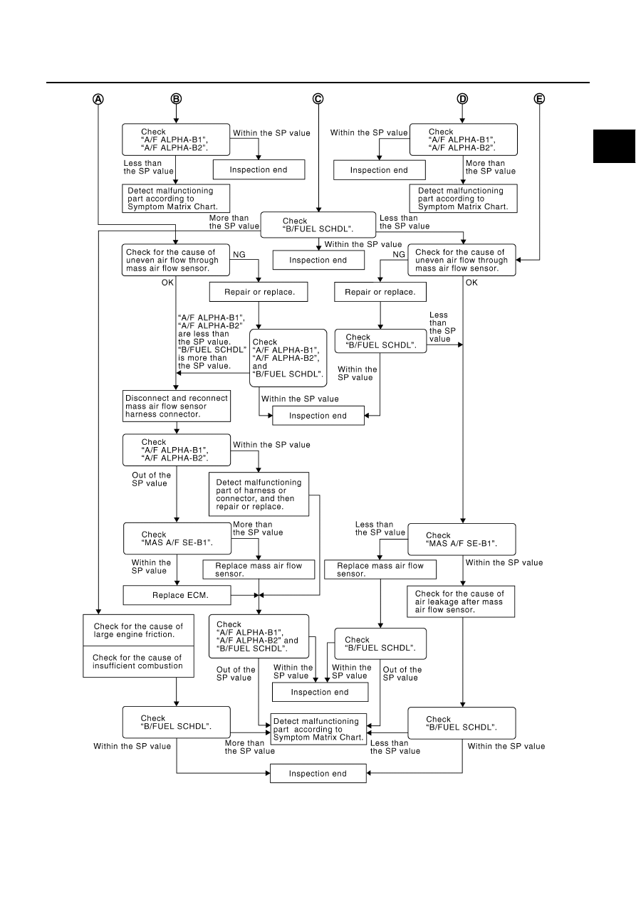
TROUBLE DIAGNOSIS - SPECIFICATION VALUE
EC-133
C
D
E
F
G
H
I
J
K
L
M
A
EC
Revision: 2006 July
2007 Murano
PBIB3214E
|
|
|
TROUBLE DIAGNOSIS - SPECIFICATION VALUE EC-133 C D E F G H I J K L M A EC Revision: 2006 July 2007 Murano PBIB3214E |