Nissan Murano Z50 (2006 year). Manual - part 24


  Index      Manuals     Nissan Murano Z50 (2006 year) - Service and Repair Manual


Search            copyright infringement  


Content      ..     22      23      24      25     ..


Nissan Murano Z50 (2006 year). Manual - part 24


NAVIGATION SYSTEM

AV-197

C

D

E

F

G

H

I

J

L

M

A

B

AV

Revision: 2006 August

2006 Murano

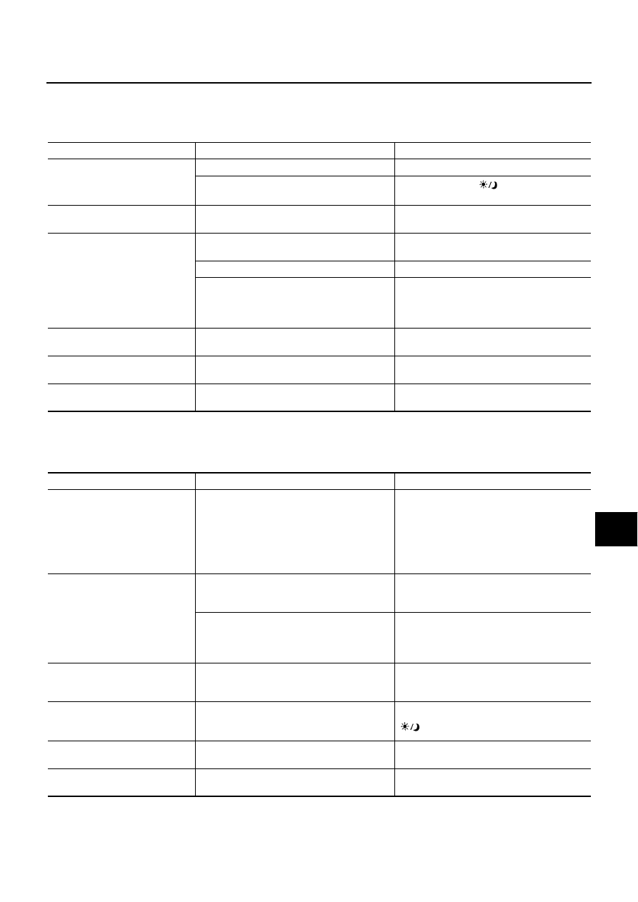
Example of Symptoms Possible No Malfunction

NKS0024Z

For Navigation System operation information, refer to Navigation System Owner's Manual.

BASIC OPERATIONS

NOTE:
Locations stored in the Address Book and other memory functions may be lost if the vehicle's battery is disconnected or is discharged. If
this occurs, service the vehicle's battery as necessary and re-enter the information in the Address Book.

VEHICLE MARKS

Symptom

Possible cause

Possible solution

No image is displayed.

The brightness is at the lowest setting.

Adjust the brightness of the display.

The display is turned off.

Press and hold the 

 button to turn on the 

display.

No voice guidance is available. or 
The volume is too high or too low.

The volume is not set correctly, or it is turned 
off.

Adjust the volume of voice guidance.

No map is displayed on the 
screen.

The DVD-ROM is not inserted, or it is inserted 
upside down.

Insert the DVD-ROM correctly.

A screen other than map screen is displayed.

Press the “MAP” button.

The pickup lens of the DVD unit is dirty.

The pickup lens can become dirty depending 
on the usage of the vehicle. Contact a NISSAN 
dealer or qualified workshop for pickup lens 
cleaning.

The screen is too dim. The move-
ment is slow.

The temperature in the interior of the vehicle is 
low.

Wait until the interior of the vehicle has 
warmed up.

Some pixels in the display are 
darker or brighter than others.

This condition is an inherent characteristic of 
liquid crystal displays.

This is not a malfunction.

Some menu items cannot be 
selected.

Some menu items become unavailable while 
the vehicle is driven.

Park the vehicle in a safe location, then oper-
ate the navigation system.

Symptom

Possible cause

Possible solution

Names of roads and locations dif-
fer between plan view and BIRD-

VIEW

  .

This is because the quantity of the displayed 
information is reduced so that the screen does 
not become difficult to read. There is also a 
chance that names of the roads or locations 
may be displayed several times, and the names 
appearing on the screen may be different 
because of a processing procedure.

This is not a malfunction.

The vehicle mark is not displayed 
in the correct position.

The vehicle was transported after the ignition 
switch was turned off, for example, by a ferry or 
car transporter.

Drive the vehicle for a while on a road where 
GPS signals can be received.

The position and direction of the vehicle mark 
may be incorrect depending on the driving envi-
ronments and the levels of positioning accuracy 
of the navigation system.

This is not a malfunction. Drive the vehicle for 
a while to automatically correct the position 
and direction of the vehicle mark.

When the vehicle is travelling on a 
new road, the vehicle mark is 
located on another road nearby.

The system automatically places the vehicle 
mark on the nearest available road, because 
the new road is not stored in the map data.

Updated road information will be included in 
the next version of the DVD-ROM.

The screen does not switch to the 
night screen even after turning on 
the headlights.

The daytime screen was set the last time the 
headlights were turned on.

Set the screen to the night screen mode using 

 button when turning on the headlights.

The map does not scroll even 
when the vehicle is moving.

The current location map screen is not dis-
played.

Press the “MAP” button.

The vehicle mark is not displayed.

The current location map screen is not dis-
played.

Press the “MAP” button.

AV-198

NAVIGATION SYSTEM

Revision: 2006 August

2006 Murano

DVD-ROM

ROUTE CALCULATION AND VISUAL GUIDANCE

The GPS indicator on the screen 
remains gray.

GPS signals cannot be received depending on 
the vehicle location, such as in a parking 
garage, on a road that has numerous tall build-
ings, etc.

Drive on an open, straight road for a while.

A sufficient amount of GPS satellites is not 
available.

Please wait for the satellites to move to loca-
tions available for the navigation system.

The location of the vehicle mark is 
misaligned from the actual posi-
tion.

When using tire chains or replacing the tires, 
speed calculations based on the speed sensor 
may be incorrect.

Drive the vehicle for a while [at approximately 
30 km/h (19 MPH) for about 30 minutes] to 
automatically correct the vehicle's mark posi-
tion. If this does not correct the vehicle mark 
position, contact a NISSAN dealer or qualified 
workshop.

The map data has a mistake or is incomplete 
(the vehicle mark position is always misaligned 
in the same area).

Updated road information will be included in 
the next version of the DVD-ROM.

Symptom

Possible cause

Possible solution

Symptom

Possible cause

Possible solution

The message “Error” appears.

The DVD-ROM is dirty or partially damaged.

Check the DVD-ROM and wipe it clean with a 
soft cloth.

If any damage, replace the DVD-ROM.

Symptom

Possible cause

Possible solution

In the auto re-route calculation, 
waypoints are not included.

Waypoints that you have already passed are 
not included in the auto re-route calculation.

To go to that waypoint again, it is necessary  to 
edit the route.

Route information is not dis-
played.

Route calculation has not yet been performed.

Set the destination and perform route calcula-
tion.

Vehicle is not driving on the suggested route.

Drive on the suggested route.

Route guidance is set to off.

Turn on the route guidance.

The auto re-route calculation (or 
detour calculation) suggests the 
same route as the one previously 
suggested.

Route calculations took priority conditions into 
consideration, but the same route was calcu-
lated.

This is not a malfunction.

A waypoint cannot be added.

Five waypoints are already set on the route, 
including the ones that you have already 
passed.

A maximum of 5 waypoints can be set on the 
route. If you want to go to 6 or more waypoints, 
perform route calculations several times, as 
necessary.

The suggested route is not dis-
played.

Roads near the destination cannot be calcu-
lated.

Reset the destination to a main or ordinary 
road, and recalculate the route.

The starting point and destination are too close.

Set a more distant destination.

The starting point and destination are too far 
away.

Divide your trip by selecting one or two inter-
mediate destinations, and perform a global 
route calculation based on multiple route cal-
culations.

There are time restricted roads (day of week, 
time) near the current vehicle location or desti-
nation.

Set [Use Time Restricted Roads] to off.

The part of the route already 
passed is deleted.

A route is managed by sections between way-
points. If passing the first waypoint, the section 
between the starting point and the waypoint is 
deleted. (It may not be deleted depending on 
the area.)

This is not a malfunction.

NAVIGATION SYSTEM

AV-199

C

D

E

F

G

H

I

J

L

M

A

B

AV

Revision: 2006 August

2006 Murano

VOICE GUIDANCE

REAR VIEW MONITOR

An indirect route is suggested.

If there are restrictions (such as one-way 
streets) on roads close to the starting point or 
destination, the system may suggest an indirect 
route.

Adjust the location of the starting point or desti-
nation.

The system may suggest an indirect route 
because route calculation does not take into 
consideration some areas such as narrow 
streets (grey roads).

Reset the destination to a main or ordinary 
road, and recalculate the route.

The landmark information does 
not correspond to the actual infor-
mation.

This may be caused by insufficient or incorrect 
data on the DVD-ROM.

Updated information will be included in the 
next version of the DVD-ROM.

The suggested route does not 
exactly connect with the starting 
point, waypoints, or destination.

There is no data for route calculation closer to 
these locations.

Set the starting point, waypoints and destina-
tion on a main road, and perform route calcula-
tion.

Symptom

Possible cause

Possible solution

Symptom

Possible cause

Possible solution

Voice guidance is not available.

Voice guidance is only available at certain inter-

sections marked with 

. In some cases, voice 

guidance is not available even when the vehicle 
should make a turn.

This is not malfunction.

The vehicle has deviated from the suggested 
route.

Go back to the suggested route or request 
route calculation again.

Voice guidance is set to off.

Turn on the voice guidance.

Route guidance is set to off.

Turn on the route guidance.

The guidance content does not 
correspond to the actual condition.

The content of voice guidance may vary, 
depending on the types of intersections where 
turns are made.

Follow all traffic rules and regulations.

Symptom

Possible cause

Possible solution

Rear view monitor image is not 
shown.

Selector lever is not set to R position.

Shift the selector lever to R position.

Rear view monitor image is fuzzy.

The front glass of the camera lens is dirty.

Wipe it with a soft wet cloth lightly.

Adherence of raindrops or snow.

Wipe it with a soft cloth lightly.

The lens is illuminated directly by sunlight or light 
from headlight of cars behind.

The fuzzy image recovers when the light is 
covered.

AV-200

NAVIGATION SYSTEM

Revision: 2006 August

2006 Murano

Removal and Installation of NAVI Control Unit

NKS00251

REMOVAL

1.

Remove center console. Refer to 

IP-17, "CENTER CONSOLE ASSEMBLY"

 . 

2.

Remove console cover (LH and RH). Refer to 

IP-17, "CENTER CONSOLE ASSEMBLY"

 .

3.

Remove control device assembly, and remove screws (2) and
nut.

4.

Disconnect NAVI control unit connector.

5.

Pull NAVI control unit up-ward, then vehicle rear side.

CAUTION:

Cover unit with cloth avoid contact with console box
bracket that may cause scratches or damages.

6.

Remove screws (4), and remove brackets.

INSTALLATION

Installation is the reverse order of removal.

PKIA2465E

PKIA2466E

PKIA2467E

NAVIGATION SYSTEM

AV-201

C

D

E

F

G

H

I

J

L

M

A

B

AV

Revision: 2006 August

2006 Murano

Removal and Installation of GPS Antenna

NKS00252

REMOVAL

1.

Remove cluster lid C. Refer to 

IP-10, "INSTRUMENT PANEL ASSEMBLY"

 .

2.

Remove center console. Refer to 

IP-17, "CENTER CONSOLE ASSEMBLY"

 .

3.

Remove console cover (LH). Refer to 

IP-17, "CENTER CONSOLE ASSEMBLY"

 .

4.

Remove display. Refer to 

AV-202, "Removal and Installation of Display"

 .

5.

Disengaged the clips (4) to separate antenna feeder.

6.

Remove screw, and remove GPS antenna.

INSTALLATION

Installation is the reverse order of removal.

Removal and Installation of A/C and AV Switch

NKS00254

Refer to 

AV-61, "Removal and Installation for A/C and AV Switch"

 .

Removal and Installation of Audio Steering Switch

NKS00253

Refer to 

AV-62, "Removal and Installation of Audio Steering Switch"

 .

PKIA2468E

PKIA2469E

AV-202

NAVIGATION SYSTEM

Revision: 2006 August

2006 Murano

Removal and Installation of Display

NKS00255

REMOVAL

1.

Remove center ventilator. Refer to 

IP-10, "INSTRUMENT PANEL ASSEMBLY"

 .

2.

Remove screws (4), and remove display.

3.

Remove screws (4), and remove brackets.

INSTALLATION

Installation is the reverse order of removal.

PKIA2473E

PKIA2474E

NAVIGATION SYSTEM

AV-203

C

D

E

F

G

H

I

J

L

M

A

B

AV

Revision: 2006 August

2006 Murano

Removal and Installation of Display Control Unit

NKS00256

REMOVAL

1.

Remove cluster lid C. Refer to 

IP-10, "INSTRUMENT PANEL ASSEMBLY"

 .

2.

Remove steering lock escutcheon. Refer to 

IP-10, "INSTRUMENT PANEL ASSEMBLY"

 .

3.

Remove screws (2), and remove display control unit.

CAUTION:

See the figure attached, when install or remove screws for
display control unit.

4.

Remove screws (4), and remove brackets.

INSTALLATION

Installation is the reverse order of removal.

PKIA2475E

PKIA2476E

AV-204

NAVIGATION SYSTEM

Revision: 2006 August

2006 Murano

Removal and Installation of Rear View Camera

NKS00257

REMOVAL

1.

Remove back door trim. Refer to 

EI-39, "BACK DOOR TRIM"

 .

2.

Unhook two pawls to remove the camera finisher from the back
door. Pull the right pawl out with pressing the rear view camera
to the left.

3.

Press the resin clip from the inside of the back door with a minus
screwdriver etc.  Remove the rear view camera from the back
door.

4.

Disconnect connector.

INSTALLATION

Installation is the reverse order of removal.
Adjust the vehicle width and distance guiding line referring to 

AV-176, "Vehicle Width and Distance Guiding

Line Correction"

  if there is a difference after installing rear view camera.

Removal and Installation of Rear View Camera Control Unit

NKS00258

REMOVAL

1.

Remove luggage floor spacer (right). Refer to 

EI-37, "LUGGAGE FLOOR TRIM"

 .

2.

Remove screw and nut.

3.

Disconnect connector, and remove rear view camera control
unit.

INSTALLATION

Installation is the reverse order of removal.

SKIB1857E

SKIB1858E

SKIB3478E

BCS-1

BODY CONTROL SYSTEM

K  ELECTRICAL

CONTENTS

C

D

E

F

G

H

I

J

L

M

SECTION 

A

B

BCS

Revision: 2006 August

2006 Murano

BODY CONTROL SYSTEM

PRECAUTIONS .......................................................... 2

Precautions for Supplemental Restraint System 
(SRS) “AIR BAG” and “SEAT BELT PRE-TEN-
SIONER” .................................................................. 2

BCM (BODY CONTROL MODULE)  ........................... 3

System Description  .................................................. 3

BCM FUNCTION ................................................... 3
COMBINATION SWITCH READING FUNCTION 

..... 3

CAN COMMUNICATION CONTROL  .................... 5
BCM STATUS CONTROL  ..................................... 6
SYSTEMS CONTROLLED BY BCM DIRECTLY 

..... 7

SYSTEMS CONTROLLED BY BCM AND IPDM 
E/R ........................................................................ 7
SYSTEMS CONTROLLED BY BCM AND COM-
BINATION METER  ................................................ 7

SYSTEMS CONTROLLED BY BCM AND INTEL-
LIGENT KEY UNIT  ................................................ 7
MAJOR COMPONENTS AND CONTROL SYS-
TEM ....................................................................... 8

CAN Communication Unit ......................................... 9
Schematic ............................................................... 10
CONSULT-II Function (BCM)  ................................. 12

CONSULT–II INSPECTION PROCEDURE ......... 12
ITEMS OF EACH PART  ...................................... 12
WORK SUPPORT  ............................................... 13

CAN Communication Inspection Using CONSULT-
II (Self-Diagnosis)  ................................................... 13
Removal and Installation of BCM  ........................... 14

REMOVAL ........................................................... 14
INSTALLATION ................................................... 14

BCS-2

PRECAUTIONS

Revision: 2006 August

2006 Murano

PRECAUTIONS

PFP:00001

Precautions for Supplemental Restraint System (SRS) “AIR BAG” and “SEAT 
BELT PRE-TENSIONER”

NKS001VF

The Supplemental Restraint System such as “AIR BAG” and “SEAT BELT PRE-TENSIONER”, used along
with a front seat belt, helps to reduce the risk or severity of injury to the driver and front passenger for certain
types of collision. This system includes seat belt switch inputs and dual stage front air bag modules. The SRS
system uses the seat belt switches to determine the front air bag deployment, and may only deploy one front
air bag, depending on the severity of a collision and whether the front occupants are belted or unbelted.
Information necessary to service the system safely is included in the SRS and SB section of this Service Man-
ual.

WARNING:

To avoid rendering the SRS inoperative, which could increase the risk of personal injury or death
in the event of a collision which would result in air bag inflation, all maintenance must be per-
formed by an authorized NISSAN/INFINITI dealer.

Improper maintenance, including incorrect removal and installation of the SRS, can lead to per-
sonal injury caused by unintentional activation of the system. For removal of Spiral Cable and Air
Bag Module, see the SRS section.

Do not use electrical test equipment on any circuit related to the SRS unless instructed to in this
Service Manual. SRS wiring harnesses can be identified by yellow and/or orange harnesses or
harness connectors.

BCM (BODY CONTROL MODULE)

BCS-3

C

D

E

F

G

H

I

J

L

M

A

B

BCS

Revision: 2006 August

2006 Murano

BCM (BODY CONTROL MODULE)

PFP:284B2

System Description

NKS001VG

BCM (Body Control Module) controls the operation of various electrical units installed on the vehicle.

BCM FUNCTION

BCM has combination switch reading function for reading the operation of combination switches (light, wiper
washer, turn signal) in addition to a function for controlling the operation of various electrical components. Also
it has an interface function allowing it to receive signals from the unified meter and A/C amp., and send signals
to ECM using CAN communication.

COMBINATION SWITCH READING FUNCTION
Description

BCM reads combination switch (lighting switch, wiper switch) status, and controls various electrical com-
ponent according to the results.

BCM reads information of a maximum of 20 switches by combining 5 output terminals (OUTPUT 1-5) and
5 input terminals (INPUT 1-5).

Operation Description

BCM activates transistors of output terminals (OUTPUT 1-5) periodically, and allows current to flow in
turn.

If any (1 or more) switches are turned ON, circuit of output terminals (OUTPUT 1-5) and input terminals
(INPUT 1-5) becomes active.

At this time, transistors of output terminals (OUTPUT 1-5) are activated to allow current to flow. When volt-
age of input terminals (INPUT 1-5) corresponding to that switch changes, interface in BCM detects volt-
age change, and BCM determines that switch is ON.

PKID0853E

BCS-4

BCM (BODY CONTROL MODULE)

Revision: 2006 August

2006 Murano

Operation Table of BCM and Combination Switches

BCM reads operation status of combination switch using combinations shown in table below.

NOTE:
Headlamp has a dual system switch.

Sample Operation: (When Lighting Switch 1ST Position Turned ON)

When lighting switch 1ST position is turned ON, contact in combination switch turns ON. At this time if
OUTPUT 4 transistor is activated, BCM detects that voltage changes in INPUT 5.

When OUTPUT 4 transistor is ON, BCM detects that voltage changes in INPUT 5, and judges that lighting
switch 1ST position is ON. Then BCM sends tail lamp ON signal to IPDM E/R using CAN communication.

When OUTPUT 4 transistor is activated again, BCM detects that voltage changes in INPUT 5, and recog-
nizes that lighting switch 1ST position is continuously ON.

NOTE:
Each OUTPUT terminal transistor is activated at 10 ms intervals. Therefore after switch is turned ON, electri-
cal loads are activated with time delay. But this time delay is so short that it cannot be detected by human
senses.

SKIA4959E

PKID0854E

BCM (BODY CONTROL MODULE)

BCS-5

C

D

E

F

G

H

I

J

L

M

A

B

BCS

Revision: 2006 August

2006 Murano

Operation Mode

Combination switch reading function has operation modes shown below.

1.

Normal status
When BCM is not in sleep status, OUTPUT terminals (1-5) send out ON signal every 10 ms.

2.

Sleep status
When BCM is in sleep status, transistors of OUTPUT 1 and 5 stop the output, and BCM enters low power
mode. Mean while OUTPUT 2, 3, and 4 send out ON signal every 60 ms, and accept input from lighting
switch system.

CAN COMMUNICATION CONTROL

CAN communication allows a high rate of information transmission through the two communication lines (CAN
L line, CAN H line) connecting the various control units in the system. Each control unit transmits/receives
data but selectively reads required data only. For details of signals that are transmitted/received by BCM via
CAN communication, refer to 

LAN-32, "CAN Communication Unit"

 .

PKIC4919E

BCS-6

BCM (BODY CONTROL MODULE)

Revision: 2006 August

2006 Murano

BCM STATUS CONTROL

BCM changes its status depending on the operation status in order to save power consumption.

1.

CAN communication status

With ignition switch ON, CAN communicates with other control units normally.

Control by BCM is being operated properly.

When ignition switch is OFF, switching to sleep mode is possible.

Even when ignition switch is OFF, if CAN communication with IPDM E/R and combination meter is
active, CAN communication status is active.

2.

Sleep transient status

This status shuts down CAN communication when ignition switch is turned OFF.

It transmits sleep request signal to IPDM E/R and combination meter.

2 seconds after CAN communication of all control units stops, sleep transient status is switched to CAN
communication inactive status.

3.

CAN communication inactive status

With ignition switch OFF, CAN communication is not active.

With ignition switch OFF, control performed only by BCM is active.

3 seconds after CAN communication of all control units stops, CAN communication inactive status is
switched to sleep status.

4.

Sleep status

BCM is activated with low power mode.

CAN communication is not active.

When CAN communication operation is detected, it switches to CAN communication status.

When a state of the following switches changes, it switches to CAN communication state.

Key switch

Hazard switch

Door lock/unlock switch

Front door switch (driver side, passenger side)

Rear door switch (LH, RH)

Back door opener switch

Combination switch (passing, lighting switch 1ST position, front fog lamp)

Key fob (lock/unlock signal)

Key cylinder switch

When control performed only by BCM is required by switch, it shifts to CAN communication inactive
mode.

BCM (BODY CONTROL MODULE)

BCS-7

C

D

E

F

G

H

I

J

L

M

A

B

BCS

Revision: 2006 August

2006 Murano

SYSTEMS CONTROLLED BY BCM DIRECTLY

NOTE:
Power supply only. No system control.

SYSTEMS CONTROLLED BY BCM AND IPDM E/R

SYSTEMS CONTROLLED BY BCM AND COMBINATION METER

SYSTEMS CONTROLLED BY BCM AND INTELLIGENT KEY UNIT

System

Reference

Power door lock system

BL-23, "POWER DOOR LOCK SYSTEM"

Remote keyless entry system

BL-58, "REMOTE KEYLESS ENTRY SYSTEM"

Power window system

 NOTE

GW-17, "POWER WINDOW SYSTEM"

Sunroof 

NOTE

RF-10, "SUNROOF"

Power seat

 NOTE

SE-92, "POWER SEAT"

Room lamp timer

LT-182, "INTERIOR ROOM LAMP"

Rear wiper and washer system

WW-37, "REAR WIPER AND WASHER SYSTEM"

System

Reference

Panic alarm

BL-58, "REMOTE KEYLESS ENTRY SYSTEM"

BL-90, "INTELLIGENT KEY SYSTEM"

Theft warning

BL-207, "VEHICLE SECURITY (THEFT WARNING) SYSTEM"

NVIS (NATS)

BL-236, "NVIS (NISSAN VEHICLE IMMOBILIZER SYSTEM-NATS)"

Headlamp, Battery saver control

LT-6, "HEADLAMP - XENON TYPE -"

LT-36, "HEADLAMP -CONVENTIONAL TYPE-"

Daytime light system

LT-64, "DAYTIME LIGHT SYSTEM"

Auto light system

LT-81, "AUTO LIGHT SYSTEM"

Front fog lamp

LT-101, "FRONT FOG LAMP"

Parking, license plate and tail lamps

LT-163, "PARKING, LICENSE PLATE AND TAIL LAMPS"

Front wiper and washer system

WW-4, "FRONT WIPER AND WASHER SYSTEM"

Rear window defogger

GW-75, "REAR WINDOW DEFOGGER"

System

Reference

Warning chime

DI-58, "WARNING CHIME"

Turn signal and hazard warning lamps

LT-114, "TURN SIGNAL AND HAZARD WARNING LAMPS"

Low tire pressure warning system

WT-8, "LOW TIRE PRESSURE WARNING SYSTEM"

System

Reference

Intelligent Key system

BL-90, "INTELLIGENT KEY SYSTEM"

BCS-8

BCM (BODY CONTROL MODULE)

Revision: 2006 August

2006 Murano

MAJOR COMPONENTS AND CONTROL SYSTEM

System

Input

Output

Remote control entry system

Key fob

All-door locking actuator

Turn signal lamp (LH, RH)

Intelligent Key system

Intelligent Key unit

All-door locking actuator

Fuel lid lock actuator

Turn signal lamp (LH, RH)

Combination meter

Power door lock system

Power window main switch
 (door lock and unlock switch)

Power window sub switch (passenger side) 
(door lock and unlock switch)

All-door locking actuator

Power supply (IGN) to power window, sunroof

Ignition power supply

Power window and sunroof system

Power supply (BAT) to power window, sunroof 
and power seat

Battery power supply

Power window, sunroof system and 
power seat

Panic alarm

Key switch

Key fob

IPDM E/R

Theft warning system

All-door switch

Key fob

Power window main switch (door lock and 
unlock switch)

IPDM E/R

Security indicator lamp

Auto light system

Optical sensor

Combination switch

Ignition switch

IPDM E/R

Battery saver control

Ignition switch

Combination switch

IPDM E/R

Headlamp

Combination switch

IPDM E/R

Daytime light system

Engine status signal

Parking brake signal

Ignition switch

Combination switch

IPDM E/R

Tail lamp

Combination switch

IPDM E/R

Front fog lamp

Combination switch

IPDM E/R

Turn signal lamp

Combination switch

Ignition switch

Turn signal lamp

Combination meter

Hazard lamp

Hazard switch

Turn signal lamp

Combination meter

Room lamp timer

Key switch

Key fob

Power window main switch (door lock and 
unlock switch)

Front door switch driver side

All-door switch

Interior room lamp

Key warning chime

Key switch

Front door switch driver side

Combination meter
(warning buzzer)

Light warning chime

Combination switch

Key switch

Front door switch driver side

Combination meter
(warning buzzer)


Content      ..     22      23      24      25     ..