Nissan Murano Z50 (2005 year). Manual - part 178


  Index      Manuals     Nissan Murano Z50 (2005 year) - Service and Repair Manual


Search            copyright infringement  


Content      ..     176      177      178      179     ..


Nissan Murano Z50 (2005 year). Manual - part 178


HEADLAMP - XENON TYPE -

LT-35

C

D

E

F

G

H

I

J

L

M

A

B

LT

Revision: 2005 August

2005 Murano

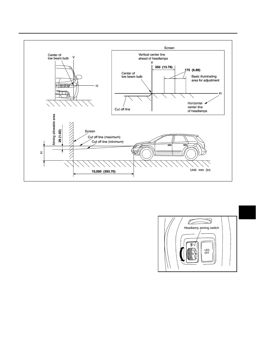
ADJUSTMENT USING AN ADJUSTMENT SCREEN (LIGHT/DARK BORDERLINE)

If the vehicle front body has been repaired and/or the headlamp assembly has been replaced, check aiming.
Use the aiming chart shown in the figure.

Basic illumination area for adjustment should be within the range shown on the aiming chart.
Adjust headlamp accordingly.

CAUTION:

Be sure aiming switch is set to “0” when performing aiming
adjustment.

PKIB2152E

PKIB2153E

LT-36

HEADLAMP - XENON TYPE -

Revision: 2005 August

2005 Murano

Bulb Replacement

AKS00AK7

HEADLAMP HIGH/LOW BEAM 

1.

Turn lighting switch OFF.

2.

Disconnect the battery cable from the negative terminal or
remove power fuse.

3.

Remove fender protector (front). Refer to 

EI-22, "FENDER

PROTECTOR"

   in “EI” section.

4.

Turn plastic cap counterclockwise and unlock it.

5.

Turn bulb socket counterclockwise and unlock it.

6.

Unlock retaining spring and remove bulb from headlamp.

7.

Installation is the reverse order of removal.

NOTE:
After installation, perform aiming adjustment. Refer to 

LT-34,

"Aiming Adjustment"

 . 

PARKING LAMP (CLEARANCE LAMP)

1.

Turn lighting switch OFF.

2.

Remove fender protector (front). Refer to 

EI-22, "FENDER PROTECTOR"

   in “EI” section.

3.

Turn bulb socket counterclockwise and unlock it.

4.

Remove bulb from its socket.

5.

Installation is the reverse order of removal.

FRONT TURN SIGNAL LAMP

1.

Turn lighting switch OFF.

2.

Remove air cleaner case (when replacing LH bulb). Refer to 

EM-16, "AIR CLEANER AND AIR DUCT"

   in

“EM” section.

3.

Remove IPDM E/R (when replacing RH bulb). Refer to 

PG-29, "Removal and Installation of IPDM E/R"

   in

“PG” section (RH).

4.

Turn bulb socket counterclockwise and unlock it.

5.

Remove bulb from its socket.

6.

Installation is the reverse order of removal.

FRONT SIDE MARKER LAMP

1.

Turn lighting switch OFF.

2.

Remove fender protector (front). Refer to 

EI-22, "FENDER PROTECTOR"

  in "EI" section.

3.

Turn bulb socket counterclockwise and unlock it.

4.

Remove bulb from its socket.

5.

Installation is the reverse order of removal.

CAUTION:

After installing bulb, be sure to install plastic cap and bulb socket securely to insure watertight-
ness.

Headlamp high/low beam (Xenon)

: 12V - 35W (D2S)

PKIA2510E

Parking lamp (Clearance lamp)

: 12V - 3.8W

Front turn signal lamp

: 12V - 21W (amber)

Front side marker lamp

: 12V - 3.8W

HEADLAMP - XENON TYPE -

LT-37

C

D

E

F

G

H

I

J

L

M

A

B

LT

Revision: 2005 August

2005 Murano

Removal and Installation

AKS00AK8

REMOVAL

1.

Disconnect the battery cable from the negative terminal or remove power fuse.

2.

Remove front bumper. Refer to 

EI-14, "FRONT BUMPER"

      in

"EI" section.

3.

Remove headlamp mounting bolts.

4.

Remove plastics bumper bracket, then pull headlamp toward
vehicle front, disconnect connector, and remove headlamp. 

INSTALLATION

Installation is the reverse order of removal. 

NOTE:
After installation, perform aiming adjustment. Refer to 

LT-34, "Aiming Adjustment"

 .

Disassembly and Assembly 

AKS00AK9

DISASSEMBLY

1.

Turn plastic cap counterclockwise and unlock it.

2.

Turn xenon bulb socket counterclockwise, and unlock it. 

3.

Unlock retaining spring, and remove xenon bulb. 

4.

Disconnect HID control unit connector, and remove HID control unit screws. 

5.

Turn parking lamp bulb socket counterclockwise and unlock it.

6.

Remove parking lamp bulb from its socket.

7.

Turn front turn signal lamp bulb socket counterclockwise and unlock it.

PKIA2511E

Headlamp mounting bolt

: 5.1 N·m (0.52 kg-m, 45 in-lb)

1.

Retaining spring

2.

Side marker lamp bulb

3.

 Side marker lamp bulb socket

4.

Seal rubber

5.

Plastic cap

6.

Xenon bulb

7.

Parking lamp bulb

8.

Parking lamp bulb socket

9.

Xenon bulb socket

10. Seal packing

11. HID control unit

12.

Front turn signal lamp bulb socket

13.  Front turn signal lamp bulb

14. Headlamp housing assembly

PKIB2154E

LT-38

HEADLAMP - XENON TYPE -

Revision: 2005 August

2005 Murano

8.

Remove front turn signal lamp bulb from its socket.

9.

Turn front side marker lamp bulb socket counterclockwise and unlock it.

10. Remove front side marker lamp bulb from its socket.

ASSEMBLY

Assembly is the reverse order of disassembly.

CAUTION:

When HID control unit is removed, reinstall it securely and avoid any looseness.

After installing bulb, be sure to install plastic cap and bulb socket securely to insure watertight-
ness. 

HID control unit mounting screw

: 3.2 N·m (0.33 kg-m, 28 in-lb)

HEADLAMP -CONVENTIONAL TYPE-

LT-39

C

D

E

F

G

H

I

J

L

M

A

B

LT

Revision: 2005 August

2005 Murano

HEADLAMP -CONVENTIONAL TYPE-

PFP:26010

Component Parts and Harness Connector Location

AKS007LL

System Description

AKS007LM

Control of the headlamp system operation is dependent upon the position of the combination switch (lighting
switch). When the lighting switch is placed in the 2ND position, the BCM (body control module) receives input
signal requesting the headlamps (and tail lamps) illuminate. This input signal is communicated to the IPDM E/
R (intelligent power distribution module engine room) across the CAN communication lines. The CPU (central
processing unit) located in the IPDM E/R controls the headlamp high and headlamp low relay coils. These
relays, when energized, direct power to the respective headlamps, which then illuminate. 

OUTLINE

Power is supplied at all times

to ignition relay, located in IPDM E/R,

to headlamp high relay located in IPDM E/R, and

to headlamp low relay located in IPDM E/R, from battery direct,

through 50A fusible link (letter F, located in fuse and fusible link block)

to BCM terminal 55,

through 10A fuse [No. 18, located in fuse block (J/B)]

to BCM terminal 42,

through 15A fuse (No. 78, located in IPDM E/R)

to CPU located in IPDM E/R,

through 10A fuse (No. 71, located in IPDM E/R)

to CPU located in IPDM E/R,

PKIB2148E

LT-40

HEADLAMP -CONVENTIONAL TYPE-

Revision: 2005 August

2005 Murano

through 10A fuse [No. 21, located in fuse block (J/B)]

to combination meter terminal 21.

With the ignition switch in the ON or START position, power is supplied

to ignition relay, located in IPDM E/R, from battery direct

through 10A fuse [No. 1, located in fuse block (J/B)]

to BCM terminal 38,

through 10A fuse [No. 14 located in fuse block (J/B)]

to combination meter terminal 20.

With the ignition switch in the ACC or ON position, power is supplied

through 10A fuse [No. 6, located in fuse block (J/B)]

to BCM terminal 11.

Ground is supplied

to BCM terminal 52

through grounds E13, E26 and E28,

to IPDM E/R terminals 38 and 60

through grounds E13, E26 and E28,

to combination meter terminals 22, 23 and 24

through grounds M14 and M78.

HEADLAMP OPERATION
Low Beam Operation

With the lighting switch in 2ND position, the BCM receives input signal requesting the headlamps to illuminate.
This input signal is communicated to the IPDM E/R across the CAN communication lines. The CPU located in
the IPDM E/R controls the headlamp low relay coil, which when energized, directs power

through 15A fuse (No. 76, located in IPDM E/R)

through IPDM E/R terminal 20

to front combination lamp RH terminal 4,

through 15A fuse (No. 86, located in IPDM E/R)

through IPDM E/R terminal 30

to front combination lamp LH terminal 4.

Ground is supplied at all times

to front combination lamp RH terminal 5

through grounds E13, E26 and E28,

to front combination lamp LH terminal 5

through grounds E13, E26 and E28.

With power and ground supplied, low beam headlamps illuminate.

High Beam Operation/Flash-to-Pass Operation

With the lighting switch in 2ND position and placed in HIGH or PASS position, the BCM receives input signal
requesting the headlamp high beams to illuminate. This input signal is communicated to the IPDM E/R across
the CAN communication lines. The CPU located in the IPDM E/R controls the headlamp high relay coil, which
when energized, directs power

through 10A fuse (No. 72, located in IPDM E/R)

through IPDM E/R terminal 27

to front combination lamp RH terminal 1,

through 10A fuse (No. 74, located in IPDM E/R)

through IPDM E/R terminal 28 

to front combination lamp LH terminal 1.

Ground is supplied

to front combination lamp RH terminal 5

through grounds E13, E26 and E28,

HEADLAMP -CONVENTIONAL TYPE-

LT-41

C

D

E

F

G

H

I

J

L

M

A

B

LT

Revision: 2005 August

2005 Murano

to front combination lamp LH terminal 5

through grounds E13, E26 and E28.

With power and ground supplied, the high beam headlamps illuminate.
The unified meter and A/C amp that received the high beam request signal by BCM across the CAN commu-
nication makes a high beam indicator lamp turn on in combination meter.

COMBINATION SWITCH READING FUNCTION

Refer to 

BCS-3, "COMBINATION SWITCH READING FUNCTION"

 .

EXTERIOR LAMP BATTERY SAVER CONTROL

When the combination switch (lighting switch) is in the 2ND position (ON), and the ignition switch is turned
from ON or ACC to OFF, the battery saver control function is activated.
Under this condition, the headlamps remain illuminated for 5 minutes, and then the headlamps are turned off.
Exterior lamp battery saver control mode can be changed by the function setting of CONSULT-II.

AUTO LIGHT OPERATION

Refer to 

LT-88, "System Description"

  in “AUTO LIGHT SYSTEM”.

VEHICLE SECURITY SYSTEM

The vehicle security system will flash the high beams if the system is triggered. Refer to 

BL-205, "VEHICLE

SECURITY (THEFT WARNING) SYSTEM"

 .

CAN Communication System Description

AKS007LN

CAN (Controller Area Network) is a serial communication line for real time application. It is an on-vehicle mul-
tiplex communication line with high data communication speed and excellent error detection ability. Many elec-
tronic control units are equipped onto a vehicle, and each control unit shares information and links with other
control units during operation (not independent). In CAN communication, control units are connected with 2
communication lines (CAN H line, CAN L line) allowing a high rate of information transmission with less wiring.
Each control unit transmits/receives data but selectively reads required data only.

CAN Communication Unit

AKS007QN

Refer to 

LAN-29, "CAN Communication Unit"

 .

LT-42

HEADLAMP -CONVENTIONAL TYPE-

Revision: 2005 August

2005 Murano

Schematic

AKS007LP

TKWB0443E

HEADLAMP -CONVENTIONAL TYPE-

LT-43

C

D

E

F

G

H

I

J

L

M

A

B

LT

Revision: 2005 August

2005 Murano

Wiring Diagram — H/LAMP —

AKS007LQ

TKWB0444E

LT-44

HEADLAMP -CONVENTIONAL TYPE-

Revision: 2005 August

2005 Murano

TKWB0445E

HEADLAMP -CONVENTIONAL TYPE-

LT-45

C

D

E

F

G

H

I

J

L

M

A

B

LT

Revision: 2005 August

2005 Murano

TKWA0745E

LT-46

HEADLAMP -CONVENTIONAL TYPE-

Revision: 2005 August

2005 Murano

TKWA0746E

HEADLAMP -CONVENTIONAL TYPE-

LT-47

C

D

E

F

G

H

I

J

L

M

A

B

LT

Revision: 2005 August

2005 Murano

Terminals and Reference Values for BCM

AKS00AKA

Terminal 

No.

Wire 

color

Signal name

Measuring condition

Reference value

Ignition 

switch

Operation or condition

2

R

Combination switch input 5

ON

Lighting, turn, wiper OFF
Wiper dial position 4

3

P/L

Combination switch input 4

ON

Lighting, turn, wiper OFF
Wiper dial position 4

4

R/G

Combination switch input 3

ON

Lighting, turn, wiper OFF
Wiper dial position 4

5

R/B

Combination switch input 2

ON

Lighting, turn, wiper OFF
Wiper dial position 4

6

R/W

Combination switch input 1

11

P/B

Ignition switch (ACC)

ACC

Battery voltage

32

LG/B

Combination switch output 5

ON

Lighting, turn, wiper OFF
Wiper dial position 4

33

G/Y

Combination switch output 4

ON

Lighting, turn, wiper OFF
Wiper dial position 4

34

LG/R

Combination switch output 3

ON

Lighting, turn, wiper OFF
Wiper dial position 4

SKIA5291E

SKIA5292E

SKIA5291E

SKIA5292E

SKIA5291E

SKIA5292E

SKIA5291E

LT-48

HEADLAMP -CONVENTIONAL TYPE-

Revision: 2005 August

2005 Murano

Terminals and Reference Values for IPDM E/R

AKS00AKB

How to Proceed With Trouble Diagnosis

AKS00AKC

1.

Confirm the symptom or customer complaint.

2.

Understand operation description and function description. Refer to 

LT-39, "System Description"

 .

3.

Perform the preliminary check. Refer to 

LT-49, "Preliminary Check"

 .

4.

Check symptom and repair or replace the cause of malfunction.

5.

Does the headlamp operate normally? If YES, GO TO 6. If NO, GO TO 4.

6.

INSPECTION END

35

G/B

Combination switch output 2

ON

Lighting, turn, wiper OFF
Wiper dial position 4

36

L/W

Combination switch output 1

38

R

Ignition switch (ON) 

ON

Battery voltage

39

L

CAN 


H

40

Y

CAN 


L

42

GR

Battery power supply

OFF

Battery voltage

52

B

Ground

ON

Approx. 0V

55

W/B

Battery power supply

OFF

Battery voltage

Terminal 

No.

Wire 

color

Signal name

Measuring condition

Reference value

Ignition 

switch

Operation or condition

SKIA5292E

Terminal 

No.

Wire 

color

Signal name

Measuring condition

Reference value

Ignition 

switch

Operation or condition

20 R/Y

Headlamp 

low 

(RH)

ON

Lighting switch 2ND 
position

OFF

Approx. 0V

ON

Battery voltage

27

L/W

Headlamp high (RH)

ON

Lighting switch HIGH 
or PASS position

OFF

Approx. 0V

ON

Battery voltage

28 

G

Headlamp high (LH)

ON

Lighting switch HIGH 
or PASS position

OFF

Approx. 0V

ON

Battery voltage

30 L

Headlamp 

low 

(LH)

ON

Lighting switch 2ND 
position

OFF

Approx. 0V

ON

Battery voltage

38

B

Ground

ON

Approx. 0V

48

L

CAN 


H

49

Y

CAN 


L

60

B

Ground

ON

Approx. 0V

HEADLAMP -CONVENTIONAL TYPE-

LT-49

C

D

E

F

G

H

I

J

L

M

A

B

LT

Revision: 2005 August

2005 Murano

Preliminary Check

AKS00AKD

CHECK POWER SUPPLY AND GROUND CIRCUIT

1. 

CHECK FUSES

Check for blown fuses.

Refer to 

LT-43, "Wiring Diagram — H/LAMP —"

 .

OK or NG

OK

>> GO TO 2.

NG

>> If fuse is blown, be sure to eliminate cause of malfunction before installing new fuse. Refer to 

PG-

3, "POWER SUPPLY ROUTING CIRCUIT"

 .

2. 

CHECK POWER SUPPLY CIRCUIT 

1.

Turn ignition switch OFF.

2.

Disconnect BCM connector.

3.

Check voltage between BCM harness connector and ground.

OK or NG

OK

>> GO TO 3.

NG

>> Check harness for open or short between BCM and

fuse.

Unit

Power source

Fuse and fusible link No.

BCM

Battery

F

18

Ignition switch ON or START position

1

Ignition switch ACC or ON position

6

IPDM E/R

Battery

72

74

76

86

Terminal

Ignition switch position

(+)

(-)

OFF

ACC

ON

Connector

Terminal 

(Wire color)

M34

11 (P/B)

Ground

Approx. 0V

Battery 
voltage

Battery 
voltage

38 (R)

Approx. 0V

Approx. 0V

Battery 
voltage

M35

42 (GR)

Battery 
voltage

Battery 
voltage

Battery 
voltage

55 (W/B)

Battery 
voltage

Battery 
voltage

Battery 
voltage

PKIB5197E

LT-50

HEADLAMP -CONVENTIONAL TYPE-

Revision: 2005 August

2005 Murano

3. 

CHECK GROUND CIRCUIT

Check continuity between BCM harness connector and ground.

OK or NG

OK

>> INSPECTION END

NG

>> Check ground circuit harness.

CONSULT-II Functions (BCM)

AKS00CRA

CONSULT-II can display each diagnostic item using the diagnostic test modes shown following.

CONSULT-II BASIC OPERATION

CAUTION:

If CONSULT-II is used with no connection of CONSULT-II CONVERTER, malfunctions might be
detected in self-diagnosis depending on control unit which carry out CAN communication. 
1.

With the ignition switch OFF, connect CONSULT-II and CON-
SULT-II CONVERTER to the data link connector, and then turn
ignition switch ON.

2.

Touch “START (NISSAN BASED VHCL)”.

Terminal

Continuity

Connector

Terminal (Wire color)

Ground

M35

52 (B)

Yes

PKIB5198E

BCM diagnosis part

Diagnosis mode

Description

HEADLAMP

WORK SUPPORT

Changes the setting for each function.

DATA MONITOR

Displays BCM input data in real time.

ACTIVE TEST

Operation of electrical loads can be checked by sending drive signal to them.

BCM

SELF-DIAG RESULTS

BCM performs self-diagnosis of CAN communication.

CAN DIAG SUPPORT MNTR

The result of transmit/receive diagnosis of CAN communication can be read.

PBIB1300E

BCIA0029E


Content      ..     176      177      178      179     ..