Nissan Murano Z50 (2005 year). Manual - part 126


  Index      Manuals     Nissan Murano Z50 (2005 year) - Service and Repair Manual


Search            copyright infringement  


Content      ..     124      125      126      127     ..


Nissan Murano Z50 (2005 year). Manual - part 126


OIL PAN AND OIL STRAINER

EM-29

C

D

E

F

G

H

I

J

K

L

M

A

EM

Revision: 2005 August

2005 Murano

OIL PAN AND OIL STRAINER

PFP:11110

Removal and Installation

ABS00FAF

REMOVAL
2WD Model

WARNING:

To avoid the danger of being scalded, do not drain engine oil when the engine is hot.
NOTE:
When removing oil pan (lower) or oil strainer only, take step 1 then step 10 and 11.

1.

Drain engine oil. Refer to 

LU-8, "Changing Engine Oil"

 .

CAUTION:

Perform this step when the engine is cold.

Do not spill engine oil on drive belts.

2.

Drain engine coolant. Refer to 

CO-9, "Changing Engine Coolant"

 .

CAUTION:

Perform this step when engine is cold.

Do not spill engine coolant on drive belts.

3.

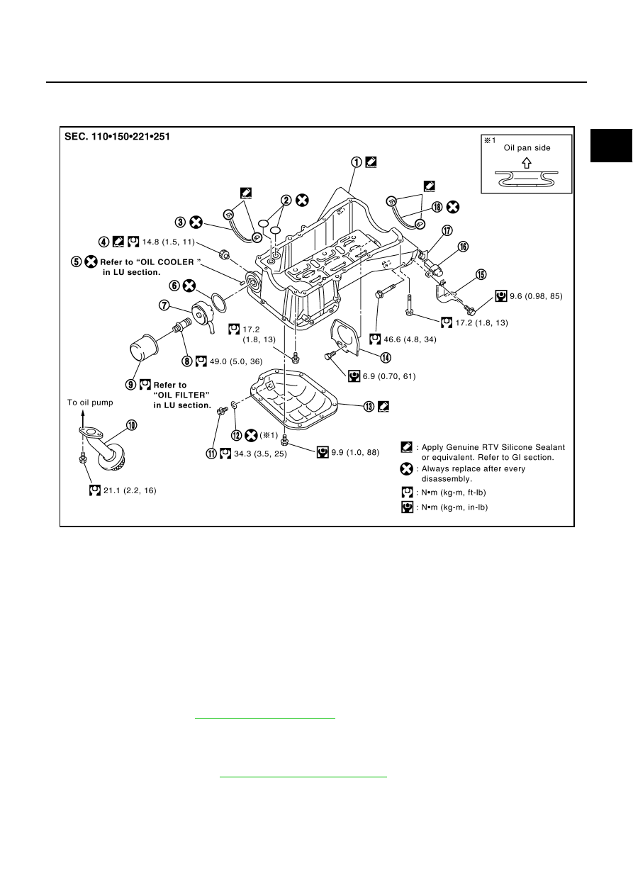
Remove following parts:

1.

Oil pan (upper)

2.

O-ring

3.

Oil pan gasket (front)

4.

Oil pressure switch

5.

Relief valve

6.

O-ring

7.

Oil cooler

8.

Connector bolt

9.

Oil filter

10. Oil strainer

11.

Drain plug

12. Drain plug washer

13. Oil pan (lower)

14. Rear plate cover

15. Harness bracket (2WD models)

16. Crankshaft position sensor (POS)

17. Seal rubber

18. Oil pan gasket (rear)

PBIC4167E

EM-30

OIL PAN AND OIL STRAINER

Revision: 2005 August

2005 Murano

Engine cover; Refer to 

EM-18, "INTAKE MANIFOLD COLLECTOR"

 .

Undercover

Splash guard (RH)

Exhaust front tube; Refer to 

EX-3, "EXHAUST SYSTEM"

 .

Drive belts; Refer to 

EM-13, "DRIVE BELTS"

 .

4.

Remove A/C compressor with piping connected, and temporarily secure it to aside. Refer to 

ATC-134,

"Components"

 .

5.

Remove three way catalysts (right and left banks) from exhaust manifolds (right and left banks). Refer to

EM-25, "EXHAUST MANIFOLD AND THREE WAY CATALYST"

 .

6.

Remove oil pressure switch. Refer to 

LU-7, "OIL PRESSURE CHECK"

 .

7.

Remove crankshaft position sensor (POS) and harness bracket.

CAUTION:

Handle carefully to avoid dropping and shocks.

Do not disassemble.

Do not allow metal powder to adhere to magnetic part at sensor tip.

Do not place sensor in a location where it is exposed to magnetism.

8.

Remove oil filter. Refer to 

LU-9, "OIL FILTER"

 .

9.

Remove oil cooler and water pipes. Refer to 

LU-10, "OIL COOLER"

 .

10. Remove oil pan (lower) as follows:

a.

Loosen mounting bolts in reverse order as shown in the figure.

b.

Insert the seal cutter [SST] between oil pan (lower) and oil pan
(upper).

CAUTION:

Be careful not to damage the mating surfaces.

Do not insert a screwdriver, this will damage the mating
surfaces.

c.

Slide the seal cutter by tapping on the side of the tool with a
hammer. Remove oil pan (lower).

11. Remove oil strainer.

12. Remove oil pan (upper) as follows:

PBIC0782E

SEM365E

PBIC1766E

OIL PAN AND OIL STRAINER

EM-31

C

D

E

F

G

H

I

J

K

L

M

A

EM

Revision: 2005 August

2005 Murano

a.

Remove transaxle joint bolts which pierce oil pan (upper). Refer
to 

CVT-232, "TRANSAXLE ASSEMBLY"

 .

b.

Loosen mounting bolts in reverse order as shown in the figure.

c.

Insert a suitable tool into the notch of oil pan (upper) as shown
(1).
Pry off oil pan (upper) by moving tool up and down as shown (2)
to remove oil pan (upper).

13. Remove O-rings from the bottom of cylinder block and oil pump.

14. Remove oil pan gaskets.

SEM949G

PBIC1636E

SEM155F

PBIC1144E

PBIC1145E

EM-32

OIL PAN AND OIL STRAINER

Revision: 2005 August

2005 Murano

AWD Model

WARNING:

To avoid the danger of being scalded, do not drain engine oil when engine is hot.
NOTE:
When removing oil pan (lower) or oil strainer only, take step 3 then step 8 and 9.

1.

Remove engine assembly from vehicle, and separate front suspension member, transaxle and transfer
assembly from engine. Refer to 

EM-107, "ENGINE ASSEMBLY"

 .

2.

install engine sub-attachment to right side of cylinder block, then lift engine, and mount it onto engine
stand. Refer to 

EM-113, "CYLINDER BLOCK"

 .

3.

Drain engine oil. Refer to 

LU-8, "Changing Engine Oil"

 .

4.

Remove oil pressure switch. Refer to 

LU-7, "OIL PRESSURE CHECK"

 .

5.

Remove oil filter. Refer to 

LU-9, "OIL FILTER"

 .

6.

Remove oil cooler and water pipes. Refer to 

LU-10, "OIL COOLER"

 .

7.

Remove three way catalysts (right and left banks) from exhaust manifolds (right and left banks). Refer to

EM-25, "EXHAUST MANIFOLD AND THREE WAY CATALYST"

 .

8.

Remove oil pan (lower) as follows:

a.

Loosen mounting bolts in reverse order as shown in the figure.

b.

Insert the seal cutter [SST] between oil pan (lower) and oil pan
(upper).

CAUTION:

Be careful not to damage the mating surfaces.

Do not insert screwdriver, this will damage the mating
surfaces.

c.

Slide the seal cutter by tapping on the side of the tool with a
hammer. Remove oil pan (lower).

9.

Remove oil strainer.

10. Remove oil pan (upper) as follows:

PBIC0782E

SEM365E

PBIC1766E

OIL PAN AND OIL STRAINER

EM-33

C

D

E

F

G

H

I

J

K

L

M

A

EM

Revision: 2005 August

2005 Murano

a.

Loosen mounting bolts in reverse order as shown in the figure.

b.

Insert a suitable tool into the notch of oil pan (upper) as shown
(1).
Pry off oil pan (upper) by moving tool up and down as shown (2)
to remove oil pan (upper).

11. Remove O-rings from the bottom of cylinder block and oil pump.

12. Remove oil pan gaskets.

INSPECTION AFTER REMOVAL

Clean oil strainer if any object attached.

INSTALLATION

1.

Install oil pan (upper) as follows:

PBIC1636E

SEM155F

PBIC1144E

PBIC1145E

EM-34

OIL PAN AND OIL STRAINER

Revision: 2005 August

2005 Murano

a.

Use a scraper to remove old liquid gasket from mating surfaces.

CAUTION:

Do not scratch or damage the mating surfaces when clean-
ing off old liquid gasket.

Also remove old liquid gasket from mating surface of cylinder
block.

Remove oil liquid gasket from bolt holes and threads.

b.

Install new oil pan gaskets.

Apply liquid gasket to new oil pan gaskets as shown in the fig-
ure.
Use Genuine RTV Silicone Sealant or equivalent. Refer to

GI-47, "RECOMMENDED CHEMICAL PRODUCTS AND
SEALANTS"

 .

To install, align protrusion of oil pan gasket with notches of
front timing chain case and rear oil seal retainer.

Install oil pan gasket with smaller arc to front timing chain
case side.

c.

Install new O-rings on the bottom of cylinder block and oil pump.

MEM108A

PBIC2630E

PBIC1145E

PBIC1144E

OIL PAN AND OIL STRAINER

EM-35

C

D

E

F

G

H

I

J

K

L

M

A

EM

Revision: 2005 August

2005 Murano

d.

Apply a continuous bead of liquid gasket with the tube presser
[SST: WS39930000 (

)] to cylinder block mating surface of

oil pan (upper) to a limited portion as shown in the figure.
Use Genuine RTV Silicone Sealant or equivalent. Refer to

GI-47, "RECOMMENDED CHEMICAL PRODUCTS AND
SEALANTS"

 .

CAUTION:

For bolt holes with   marks (5 locations), apply liquid
gasket outside the holes.

Apply a bead of 4.5 to 5.5 mm (0.177 to 0.217 in) diameter
to area “A”.

Attaching should be done within 5 minutes after coating.

e.

Install oil pan (upper).

CAUTION:

Install avoiding misalignment of both oil pan gasket and O-rings.

Tighten mounting bolts in numerical order as shown in the fig-
ure.

There are two types of mounting bolt. Refer to the following
for locating bolts.

f.

Install transaxle joint bolts. (2WD models) Refer to 

CVT-232, "TRANSAXLE ASSEMBLY"

 .

2.

Install oil strainer to oil pump.

3.

Install oil pan (lower) as follows:

a.

Use scraper to remove old liquid gasket from mating surfaces.

Also remove old liquid gasket from mating surface of oil pan
(upper).

Remove old liquid gasket from the bolt holes and thread.

CAUTION:

Do not scratch or damage the mating surfaces when clean-
ing off old liquid gasket.

M8 

×

 100 mm (3.97 in)

: 5, 7, 8, 11

M8 

×

 25 mm (0.98 in)

: Except the above

PBIC2300E

PBIC1636E

SEM958F

EM-36

OIL PAN AND OIL STRAINER

Revision: 2005 August

2005 Murano

b.

Apply a continuous bead of liquid gasket with the tube presser
[SST: WS39930000 (

)] to oil pan (lower) as shown in the

figure.
Use Genuine RTV Silicone Sealant or equivalent. Refer to

GI-47, "RECOMMENDED CHEMICAL PRODUCTS AND
SEALANTS"

 .

CAUTION:

Attaching should be done within 5 minutes after coating.

c.

Install oil pan (lower).

Tighten mounting bolts in numerical order as shown in the fig-
ure.

4.

Install oil pan drain plug.

Refer to the figure of components of former page for installation direction of drain plug washer. Refer to

EM-29, "Removal and Installation"

 .

5.

Install in the reverse order of removal after this step.

NOTE:
At least 30 minutes after oil pan is installed, pour engine oil.

INSPECTION AFTER INSTALLATION
Inspection for Leaks

The following are procedures for checking fluids leak, lubricates leak and exhaust gases leak.

Before starting engine, check oil/fluid levels including engine coolant and engine oil. If less than required
quantity, fill to the specified level. Refer to 

MA-10, "RECOMMENDED FLUIDS AND LUBRICANTS"

 .

Use procedure below to check for fuel leakage.

Turn ignition switch “ON” (with engine stopped). With fuel pressure applied to fuel piping, check for fuel
leakage at connection points.

Start engine. With engine speed increased, check again for fuel leakage at connection points.

Run engine to check for unusual noise and vibration.

Warm up engine thoroughly to make sure there is no leakage of fuel, exhaust gases, or any oil/fluids
including engine oil and engine coolant.

Bleed air from lines and hoses of applicable lines, such as in cooling system.

PBIC2657E

PBIC0782E

OIL PAN AND OIL STRAINER

EM-37

C

D

E

F

G

H

I

J

K

L

M

A

EM

Revision: 2005 August

2005 Murano

After cooling down engine, again check oil/fluid levels including engine oil and engine coolant. Refill to the
specified level, if necessary.

Summary of the inspection items:

* Transmission/transaxle/CVT fluid. power steering fluid, brake fluid, etc.

Item

Before starting engine

Engine running

After engine stopped

Engine coolant

Level

Leakage

Level

Engine oil

Level

Leakage

Level

Other oils and fluid*

Level

Leakage

Level

Fuel

Leakage

Leakage

Leakage

Exhaust gases

Leakage

EM-38

IGNITION COIL

Revision: 2005 August

2005 Murano

IGNITION COIL

PFP:22448

Removal and Installation

ABS0032I

REMOVAL

1.

Remove engine cover. Refer to 

EM-18, "INTAKE MANIFOLD COLLECTOR"

 .

2.

Remove front wiper arm and extension cowl top (lower and upper). Refer to 

WW-4, "FRONT WIPER AND

WASHER SYSTEM"

 an

EI-21, "COWL TOP"

 .

3.

Remove intake manifold collectors (upper and lower). (At the right bank side, remove ignition coil) Refer to

EM-18, "INTAKE MANIFOLD COLLECTOR"

 .

4.

Move aside harness, harness bracket, and hoses located above ignition coil.

5.

Disconnect harness connector from ignition coil.

6.

Remove ignition coil.

CAUTION:

Do not drop or shock it.

INSTALLATION

Install in the reverse order of removal.

1.

Ignition coil

2.

Spark plug

PBIC2466E

SPARK PLUG (PLATINUM-TIPPED TYPE)

EM-39

C

D

E

F

G

H

I

J

K

L

M

A

EM

Revision: 2005 August

2005 Murano

SPARK PLUG (PLATINUM-TIPPED TYPE)

PFP:22401

Removal and Installation

ABS0033P

REMOVAL

1.

Remove engine cover. Refer to 

EM-18, "INTAKE MANIFOLD COLLECTOR"

 .

2.

Remove ignition coil. Refer to 

EM-38, "IGNITION COIL"

 .

3.

Remove spark plug using spark plug wrench (commercial ser-
vice tool).

CAUTION:

Do not drop or shock it.

INSPECTION AFTER REMOVAL

Use the standard type spark plug for normal condition.

The hot type spark plug is suitable when fouling occurs with the standard type spark plug under conditions 
such as:

Frequent engine starts

Low ambient temperatures

The cold type spark plug is suitable when spark plug knock occurs with the standard type spark plug under 
conditions such as:

Extended highway driving

Frequent high engine revolution

1.

Ignition coil

2.

Spark plug

PBIC2466E

SEM294A

Make

NGK

Standard type

PLFR5A-11

Hot type

PLFR4A-11

Cold type

PLFR6A-11

Gap (Nominal)

: 1.1 mm (0.043 in)

EM-40

SPARK PLUG (PLATINUM-TIPPED TYPE)

Revision: 2005 August

2005 Murano

CAUTION:

Do not drop or shock spark plug.

Do not use wire brush for cleaning.

If plug tip is covered with carbon, spark plug cleaner may
be used.

Checking and adjusting plug gap is not required between
change intervals.

INSTALLATION

Install in the reverse order of removal.

Cleaner air pressure:

Less than 588 kPa (6 kg/cm

2

 , 85 psi)

Cleaning time:

Less than 20 seconds

SMA773C

SMA806CA

FUEL INJECTOR AND FUEL TUBE

EM-41

C

D

E

F

G

H

I

J

K

L

M

A

EM

Revision: 2005 August

2005 Murano

FUEL INJECTOR AND FUEL TUBE

PFP:16600

Removal and Installation

ABS0032K

CAUTION:

Do not remove or disassemble parts unless instructed as shown in the figure.

REMOVAL

WARNING:

Put a “CAUTION INFLAMMABLE” sign in the workshop.

Be sure to work in a well ventilated area and furnish workshop with a CO

2

     fire extinguisher.

Do not smoke while servicing fuel system. Keep open flames and sparks away from the work area.

To avoid the danger of being scalded, do not drain engine coolant when engine is hot.

1.

Remove engine cover. Refer to 

EM-18, "INTAKE MANIFOLD COLLECTOR"

 .

2.

Release the fuel pressure. Refer to 

EC-92, "FUEL PRESSURE RELEASE"

 .

3.

Drain engine coolant, or when water hoses are disconnected, attach plug to prevent engine coolant leak-
age. Refer to 

CO-9, "Changing Engine Coolant"

 an

EM-18, "INTAKE MANIFOLD COLLECTOR"

 .

CAUTION:

Perform this step when the engine is cold.

4.

Remove front wiper arm and extension cowl top panel (lower and upper). Refer to 

WW-4, "FRONT

WIPER AND WASHER SYSTEM"

 and 

EI-21, "COWL TOP"

 .

1.

Quick connector cap

2.

Centralized under-floor piping

3.

Fuel feed hose (with damper)

4.

Fuel tube

5.

Spacer

6.

Clip

7.

O-ring (blue)

8.

Fuel injector

9.

O-ring (brown)

10. O-ring

11.

Fuel damper

PBIC2677E

EM-42

FUEL INJECTOR AND FUEL TUBE

Revision: 2005 August

2005 Murano

5.

Remove radiator cover grilles, air duct (inlet), air cleaner case (upper) with mass air flow sensor and air
duct assembly. Refer to 

EM-16, "AIR CLEANER AND AIR DUCT"

 .

6.

Remove intake manifold collectors (upper and lower). Refer to 

EM-18, "INTAKE MANIFOLD COLLEC-

TOR"

 .

Intake manifold collector (upper) should be moved aside with water hoses connected.

7.

Remove fuel feed hose (with damper) from fuel tube.

CAUTION:

While hose disconnected, plug it to prevent fuel from
draining.

Do not separate fuel damper and fuel feed hose.

8.

When separating fuel feed hose (with damper) and centralized under-floor piping connection, disconnect
quick connector as follows:

a.

Remove quick connector cap from quick connector.

b.

Disconnect quick connector from centralized under-floor piping
as follows:

CAUTION:

Disconnect quick connector by using the quick connector
release [SST: J-45488], not by picking out retainer tabs.

i.

With the sleeve side of quick connector release facing to quick
connector, install the quick connector release onto fuel tube.

ii.

Insert the quick connector release into quick connector until
sleeve contacts and goes no further. Hold quick connector
release on that position.

CAUTION:

Inserting quick connector release hard will not disconnect
quick connector. Hold quick connector release where it
contacts and goes no further.

iii.

Draw and pull out quick connector straight from centralized
under-floor piping.

CAUTION:

Pull quick connector holding “A” position as shown in
the figure.

Do not pull with lateral force applied. O-ring inside quick connector may be damaged.

Prepare container and cloth beforehand as fuel will leak out.

PBIC2468E

PBIC1178E

PBIC1179E

PBIC1898E

FUEL INJECTOR AND FUEL TUBE

EM-43

C

D

E

F

G

H

I

J

K

L

M

A

EM

Revision: 2005 August

2005 Murano

Avoid fire and sparks.

Keep parts away from heat source. Especially, be careful when welding is performed around
them.

Do not expose parts to battery electrolyte or other acids.

Do not bend or twist connection between quick connector and fuel feed hose (with damper) dur-
ing installation/removal.

To keep clean the connecting portion and to avoid dam-
age and foreign materials, cover them completely with
plastic bags or something similar.

9.

Disconnect harness connector from fuel injector.

10. Loosen mounting bolts in reverse order as shown in the figure,

and remove fuel tube and fuel injector assembly.

CAUTION:

Do not tilt it, or remaining fuel in pipes may flow out from
pipes.

11. Remove spacers on intake manifold.
12. Remove fuel injector from fuel tube as follows:

a.

Open and remove clip.

b.

Remove fuel injector from fuel tube by pulling straight.

CAUTION:

Be careful with remaining fuel that may go out from fuel
tube.

Be careful not to damage injector nozzle during removal.

Do not bump or drop fuel injector.

Do not disassemble fuel injector.

13. Remove fuel damper from fuel tube.

PBIC1899E

SEC999C

PBIC2470E

EM-44

FUEL INJECTOR AND FUEL TUBE

Revision: 2005 August

2005 Murano

INSTALLATION

1.

Install fuel damper.

When handling new O-rings, be careful of the following caution:

CAUTION:

Handle O-ring with bare hands. Do not wear gloves.

Lubricate O-ring with new engine oil.

Do not clean O-ring with solvent.

Make sure that O-ring and its mating part are free of foreign material.

When installing O-ring, be careful not to scratch it with tool or fingernails. Also be careful not
to twist or stretch O-ring. If O-ring was stretched while it was being attached, do not insert it
quickly into fuel tube.

Insert new O-ring straight into fuel damper. Do not decenter or twist it.

Insert fuel damper straight into fuel tube.

Tighten mounting bolts evenly in turn.

After tightening mounting bolts, make sure that there is no gap between flange and fuel tube.

2.

Install new O-rings to fuel injector paying attention to the following.

CAUTION:

Upper and lower O-ring are different. Be careful not to confuse them.

Handle O-ring with bare hands. Never wear gloves.

Lubricate O-ring with new engine oil.

Do not clean O-ring with solvent.

Make sure that O-ring and its mating part are free of foreign material.

When installing O-ring, be careful not to scratch it with tool or fingernails. Also be careful not to
twist or stretch O-ring. If O-ring was stretched while it was being attached, do not insert it
quickly into fuel tube.

Insert O-ring straight into fuel injector. Do not decenter or twist it.

3.

Install fuel injector to fuel tube as follows:

a.

Insert clip into clip mounting groove on fuel injector.

Insert clip so that protrusion “A” of fuel injector matches cutout
“A” of  clip.

CAUTION:

Do not reuse clip. Replace it with new one.

Be careful to keep clip from interfering with O-ring. If
interference occurs, replace O-ring.

b.

Insert fuel injector into fuel tube with clip attached.

Insert it while matching it to the axial center.

Insert fuel injector so that protrusion “B” of fuel tube matches
cutout “B” of clip.

Make sure that fuel tube flange is securely fixed in flange fix-
ing groove on clip.

c.

Make sure that installation is complete by checking that fuel
injector does not rotate or come off.

Make sure that protrusions of fuel injectors are aligned with
cutouts of clips after installation.

Fuel tube side

: Blue

Nozzle side

: Brown

PBIC2545E


Content      ..     124      125      126      127     ..