Nissan Murano Z50 (2005 year). Manual - part 67


  Index      Manuals     Nissan Murano Z50 (2005 year) - Service and Repair Manual


Search            copyright infringement  


Content      ..     65      66      67      68     ..


Nissan Murano Z50 (2005 year). Manual - part 67


DTC P0845 TRANSMISSION FLUID PRESSURE SENSOR B CIRCUIT (PRI 

PRESSURE SENSOR)

CVT-149

D

E

F

G

H

I

J

K

L

M

A

B

CVT

Revision: 2005 August

2005 Murano

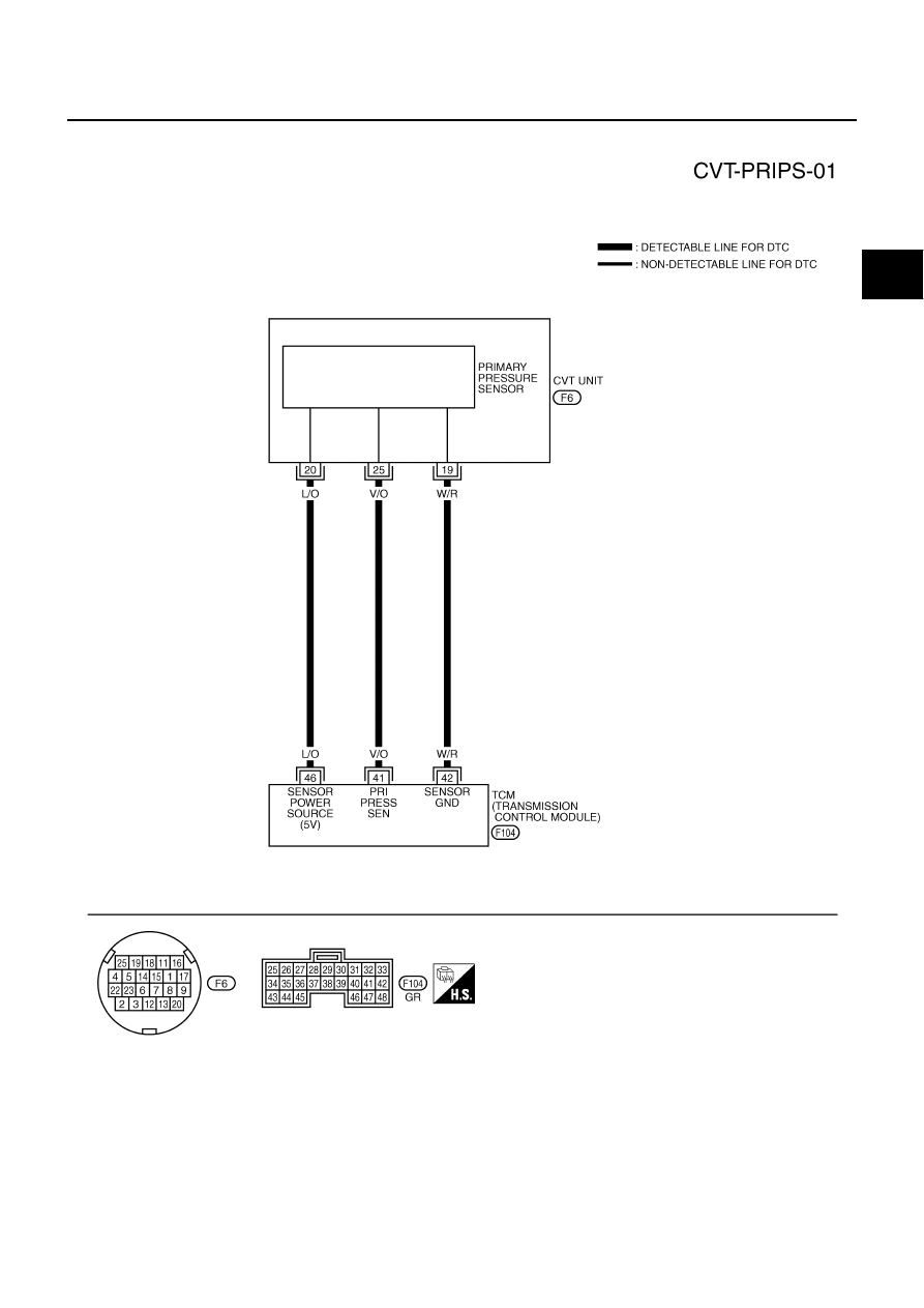
Wiring Diagram — CVT — PRIPS

ACS002TV

TCWA0255E

CVT-150

DTC P0845 TRANSMISSION FLUID PRESSURE SENSOR B CIRCUIT (PRI 

PRESSURE SENSOR)

Revision: 2005 August

2005 Murano

TCM terminal data are reference values, measured between each terminal and ground.

Diagnostic Procedure

ACS002TW

1. 

CHECK INPUT SIGNAL

 With CONSULT-II

1.

Start engine.

2.

Select “ECU INPUT SIGNALS” in “DATA MONITOR” mode for
“TRANSMISSION” with CONSULT-II.

3.

Start vehicle and read out the value of “PRI HYDR SEN”.

 Without CONSULT-II

1.

Start engine.

2.

Check voltage between TCM connector terminal and ground.

OK or NG

OK

>> GO TO 5.

NG

>> GO TO 2.

Terminal

Wire color

Item

Condition

Data (Approx.)

41

V/O

Transmission fluid 
pressure sensor B 
(Primary pressure 
sensor)

and

“N” position idle

0.7 - 3.5V

42

W/R

Sensor ground

Always

 0V

46

L/O

Sensor power

 4.5 - 5.5V


0V

Monitor item

Condition

Display value (Approx.)

PRI HYDR SEN

“N” position idle

 0.7 - 3.5V

SCIA2277E

 Name

 Connector

 Terminal

(Wire color)

 Condition

 Voltage 

(Approx.)

Transmis-
sion fluid 
pressure 
sensor B 
(Primary 
pressure 
sensor)

 F104

 41 (V/O) - 

Ground

“ N” position idle

 0.7 - 3.5V

SCIA4509E

DTC P0845 TRANSMISSION FLUID PRESSURE SENSOR B CIRCUIT (PRI 

PRESSURE SENSOR)

CVT-151

D

E

F

G

H

I

J

K

L

M

A

B

CVT

Revision: 2005 August

2005 Murano

2. 

CHECK SENSOR POWER AND SENSOR GROUND

1.

Turn ignition switch ON. (Do not start engine)

2.

Check voltage between TCM connector terminals.

OK or NG

OK

>> GO TO 4.

NG

>> GO TO 3.

3. 

 CHECK HARNESS BETWEEN TCM AND CVT UNIT HARNESS CONNECTOR (SENSOR POWER 

AND SENSOR GROUND)

1.

Turn ignition switch OFF.

2.

Disconnect TCM connector and CVT unit harness connector.

3.

Check continuity between TCM connector terminal and CVT unit
harness connector terminal.

4.

If OK, check harness for short to ground and short to power.

5.

Reinstall any part removed.

 OK or NG

 OK

>> Replace TCM. Refer to 

CVT-9, "Precautions for TCM and CVT Assembly Replacement"

 .

 NG

>> Repair open circuit or short to ground or short to power in harness or connectors.

4. 

CHECK HARNESS BETWEEN TCM AND TRANSMISSION FLUID PRESSURE SENSOR B (PRIMARY 

PRESSURE SENSOR)

1.

Turn ignition switch OFF.

2.

Disconnect TCM connector.

3.

Check continuity between TCM connector terminal and CVT unit
harness connector terminal.

4.

If OK, check harness for short to ground and short to power.

5.

Reinstall any part removed.

OK or NG

OK

>> GO TO 5.

NG

>> Repair open circuit or short to ground or short to power in harness or connectors.

Item

Connector

 Terminal

(Wire color)

Data 

(Approx.)

TCM connector

F104

46 (L/O) - 42 (W/R) 

4.5 - 5.5V

SCIA2367E

 Item

 Connector

 Terminal

(Wire color)

 Continuity

 TCM

 F104

 42 (W/R)

 Yes

 CVT unit harness connector

 F6

 19 (W/R)

 TCM

 F104

 46 (L/O)

 Yes

 CVT unit harness connector

 F6

 20 (L/O)

SCIA4681E

Item

Connector

 Terminal

(Wire color)

Continuity

TCM

F104

41 (V/O)

Yes

CVT unit harness connector

F6

25 (V/O)

SCIA4691E

CVT-152

DTC P0845 TRANSMISSION FLUID PRESSURE SENSOR B CIRCUIT (PRI 

PRESSURE SENSOR)

Revision: 2005 August

2005 Murano

5. 

CHECK DTC

Perform “DTC Confirmation Procedure”. Refer to 

CVT-148, "DTC Confirmation Procedure"

 .

OK or NG

OK

>> INSPECTION END

NG

>> GO TO 6.

6. 

CHECK TCM

1.

Check TCM input/output signal. Refer to 

CVT-58, "TCM Input/Output Signal Reference Values"

 .

2.

If NG, re-check TCM pin terminals for damage or loose connection with harness connector.

OK or NG

OK

>> Replace the transaxle assembly. Refer to 

CVT-232, "Removal and Installation"

 .

NG

>> Repair or replace damaged parts.

DTC P0868 SECONDARY PRESSURE DOWN

CVT-153

D

E

F

G

H

I

J

K

L

M

A

B

CVT

Revision: 2005 August

2005 Murano

DTC P0868 SECONDARY PRESSURE DOWN

PFP:31941

Description

ACS002TX

The pressure control solenoid valve B (secondary pressure solenoid valve) regulates the secondary pressure
to suit the driving condition in response to a signal sent from the TCM.

CONSULT-II Reference Value

ACS002TY

Remarks: Specification data are reference values.

On Board Diagnosis Logic

ACS002TZ

This is not an OBD-II self-diagnostic item. 

Diagnostic trouble code “P0868 SEC/PRESS DOWN” with CONSULT-II is detected when secondary fluid
pressure is too low compared with the commanded value while driving.

Possible Cause

ACS002U0

Harness or connectors
(Solenoid circuit is open or shorted.)

Pressure control solenoid valve B (Secondary pressure solenoid valve) system

Transmission pressure sensor A (Secondary pressure sensor)

Line pressure control system

DTC Confirmation Procedure

ACS002U1

CAUTION:

Always drive vehicle at a safe speed.

Be careful not to rev engine into the red zone on the tachometer.

NOTE:
If “DTC Confirmation Procedure” has been previously performed, always turn ignition switch OFF and
wait at least 5 seconds before performing the next test.
After the repair, perform the following procedure to confirm the malfunction is eliminated.

 WITH CONSULT-II

1.

Turn ignition switch ON and select “DATA MONITOR” mode for
“TRANSMISSION” with CONSULT-II.

2.

Make sure that output voltage of CVT fluid temperature sensor
is within the range below.
FLUID TEMP SEN: 1.0 - 2.0V
If out of range, drive the vehicle to decrease the voltage
(warm up the fluid) or stop engine to increase the voltage
(cool down the fluid)

3.

Start engine and maintain the following conditions for at least 10
consecutive seconds.
VEHICLE SPEED (accelerate slowly): 0 

 50 km/h (31 MPH)

ACC PEDAL OPEN: 0.5/8 - 1.0/8
Selector lever: “D” position

4.

If DTC is detected, go to 

CVT-154, "Diagnostic Procedure"

 .

Monitor item

Condition

Display value (Approx.)

SEC PRESS

 “N” position idle

0.5 - 0.9MPa

BCIA0031E

CVT-154

DTC P0868 SECONDARY PRESSURE DOWN

Revision: 2005 August

2005 Murano

Diagnostic Procedure

ACS002U2

1. 

CHECK INPUT SIGNAL

 With CONSULT-II

1.

Start engine.

2.

Select “MAIN SIGNALS” in “DATA MONITOR” mode for
“TRANSMISSION” with CONSULT-II.

3.

Start vehicle and read out the value of “SEC PRESS”.

OK or NG

OK

>> GO TO 5.

NG

>> GO TO 2.

2. 

CHECK LINE PRESSURE

Perform line pressure test. Refer to 

CVT-44, "LINE PRESSURE

TEST"

 .

OK or NG

OK

>> GO TO 3.

NG

>> Repair or replace damaged parts. Refer to 

CVT-45,

"Judgement of Line Pressure Test"

 .

3. 

DETECT MALFUNCTIONING ITEM

Check the following:

Pressure control solenoid valve B (Secondary pressure solenoid valve). Refer to 

CVT-134, "Component

Inspection"

 .

Pressure control solenoid valve A (Line pressure solenoid valve). Refer to 

CVT-123, "Component Inspec-

tion"

 .

OK or NG

OK

>> GO TO 4.

NG

>> Repair or replace damaged parts.

4. 

CHECK TRANSMISSION FLUID PRESSURE SENSOR A (SECONDARY PRESSURE SENSOR) SYS-

TEM

Check transmission fluid pressure sensor A (secondary pressure sensor) system. Refer to 

CVT-140, "DTC

P0840 TRANSMISSION FLUID PRESSURE SENSOR A CIRCUIT (SEC PRESSURE SENSOR)"

 .

OK or NG

OK

>> GO TO 5.

NG

>> Repair or replace damaged parts.

Monitor item

Condition

Display value (Approx.)

SEC PRESS

 “N” position idle

0.5 - 0.9MPa

SCIA2366E

SAT494G

DTC P0868 SECONDARY PRESSURE DOWN

CVT-155

D

E

F

G

H

I

J

K

L

M

A

B

CVT

Revision: 2005 August

2005 Murano

5. 

DETECT MALFUNCTIONING ITEM

Check the following:

Power supply and ground circuit for TCM. Refer to 

CVT-157, "Wiring Diagram — CVT — POWER"

 .

The TCM pin terminals for damage or loose connection with harness connector.

OK or NG

OK

>> GO TO 6.

NG

>> Repair or replace damaged parts.

6. 

CHECK DTC

Perform “DTC Confirmation Procedure”. Refer to 

CVT-153, "DTC Confirmation Procedure"

 .

OK or NG

OK

>> INSPECTION END

NG

>> Replace the transaxle assembly. Refer to 

CVT-232, "Removal and Installation"

 .

CVT-156

DTC P1701 TRANSMISSION CONTROL MODULE (POWER SUPPLY)

Revision: 2005 August

2005 Murano

DTC P1701 TRANSMISSION CONTROL MODULE (POWER SUPPLY)

PFP:31036

Description

ACS0064C

When the power supply to the TCM is cut OFF, for example because the battery is removed, and the self-diag-
nosis memory function stops, malfunction is detected.
NOTE:
Since “P1701 TCM-POWER SUPPLY” will be indicated when replacing TCM, perform diagnosis after
erasing “SELF-DIAG RESULTS”

On Board Diagnosis Logic

ACS0064D

This is not an OBD-II self-diagnostic item.

Diagnostic trouble code “P1701 TCM-POWER SUPPLY” with CONSULT-II is detected when TCM does
not receive the voltage signal from the battery power supply.

This is not a malfunction message. (Whenever shutting OFF a power supply to the TCM, this message
appears on the screen.)

Possible Cause

ACS0064E

Harness or connectors
(Battery or ignition switch and TCM circuit is open or shorted.)

DTC Confirmation Procedure

ACS0064F

NOTE:
If “DTC Confirmation Procedure” has been previously conducted, always turn ignition switch OFF and
wait at least 10 seconds before conducting the next test.
After the repair, perform the following procedure to confirm the malfunction is eliminated.

 WITH CONSULT-II

1.

Turn ignition switch ON. (Do not start engine.)

2.

Turn ignition switch ON and select “DATA MONITOR” mode for
“TRANSMISSION” with CONSULT-II.

3.

Wait for at least 2 consecutive seconds.

4.

If DTC is detected, go to 

CVT-158, "Diagnostic Procedure"

 .

BCIA0031E

DTC P1701 TRANSMISSION CONTROL MODULE (POWER SUPPLY)

CVT-157

D

E

F

G

H

I

J

K

L

M

A

B

CVT

Revision: 2005 August

2005 Murano

Wiring Diagram — CVT — POWER

ACS0064J

TCWA0259E

CVT-158

DTC P1701 TRANSMISSION CONTROL MODULE (POWER SUPPLY)

Revision: 2005 August

2005 Murano

TCM terminals data are reference values, measured between each terminal and ground.

Diagnostic Procedure

ACS0064K

1. 

CHECK DTC 

1.

Turn ignition switch ON. (Do not start engine.)

2.

Select “SELF-DIAG RESULTS” mode for “TRANSMISSION”
with CONSULT-II.

3.

Erase self-diagnostic results. Refer to 

CVT-31, "HOW TO

ERASE DTC (WITH CONSULT-II)"

 .

4.

Turn ignition switch OFF, and wait for 5 seconds or more.

5.

Start engine.

6.

Confirm self-diagnostic results again. Refer to 

CVT-67, "SELF-

DIAGNOSTIC RESULT MODE"

 .

Is the “P1701 TCM-POWER SUPPLY” displayed?

YES

>> GO TO 2.

NO

>> INSPECTION END

2. 

CHECK TCM POWER SOURCE, STEP 1

1.

Turn ignition switch OFF.

2.

Check voltage between TCM connector terminal and ground.

OK or NG

OK

>> GO TO 3.

NG

>> GO TO 4.

Terminal

Wire color

Item

Condition

Data (Approx.)

10

Y/L

Power supply

Battery voltage

0V

19

Y/L

Power supply

Battery voltage

0V

25

B

Ground

Always

0V

28

Y/R

Power supply 
(memory back-up)

Always

Battery voltage

48

B

Ground

Always

0V

BCIA0031E

 Name

 Connector

 Terminal

(Wire color)

 Condition

 Voltage 

(Approx.)

Power supply 
(memory back-
up)

 F104

 28 (Y/R) - 

Ground

Always

Battery 
voltage

SCIA4783E

DTC P1701 TRANSMISSION CONTROL MODULE (POWER SUPPLY)

CVT-159

D

E

F

G

H

I

J

K

L

M

A

B

CVT

Revision: 2005 August

2005 Murano

3. 

CHECK TCM POWER SOURCE, STEP 2

1.

Turn ignition switch ON. (Do not start engine.)

2.

Check voltage between TCM connector terminals and ground.

OK or NG

OK

>> GO TO 5.

NG

>> GO TO 4.

4. 

DETECT MALFUNCTIONING ITEM

Check the following.

Harness for short or open between battery and TCM connector terminal 28

Harness for short or open between ignition switch and TCM connector terminal 10, 19

10A fuse (No.83, located in the IPDM E/R) 

10A fuse (No.19, located in the fuse block) 

Ignition switch. Refer to 

PG-3, "POWER SUPPLY ROUTING CIRCUIT"

 .

OK or NG

OK

>> GO TO 5.

NG

>> Repair or replace damaged parts. 

5. 

CHECK TCM GROUND CIRCUIT

1.

Turn ignition switch OFF.

2.

Disconnect TCM connector.

3.

Check continuity between TCM connector terminals and ground.

OK or NG

OK

>> GO TO 6.

NG

>> Repair open circuit or short to ground or short to power

in harness or connectors.

 Name

 Connector

 Terminal

(Wire color)

 Condition

 Voltage 

(Approx.)

Power supply

 F103

 10 (Y/L) - 

Ground

Battery 
voltage

0V

Power supply

 19 (Y/L) - 

Ground

Battery 
voltage

0V

Power supply 
(memory 
back-up)

 F104

 28 (Y/R) - 

Ground

Always

Battery 
voltage

SCIA4784E

 Name

 Connector

 Terminal

(Wire color)

Continuity

Ground

F104

25 (B)

Yes

48 (B)

SCIA2671E

CVT-160

DTC P1701 TRANSMISSION CONTROL MODULE (POWER SUPPLY)

Revision: 2005 August

2005 Murano

6. 

CHECK DTC

Check again. Refer to 

CVT-158, "Diagnostic Procedure"

 .

OK or NG

OK

>> INSPECTION END

NG

>> GO TO 7.

7. 

CHECK TCM

1.

Check TCM input/output signal. Refer to 

CVT-58, "TCM Input/Output Signal Reference Values"

 .

2.

If NG, re-check TCM pin terminals for damage or loose connection with harness connector.

OK or NG

OK

>> INSPECTION END

NG

>> Repair or replace damaged parts.

DTC P1705 THROTTLE POSITION SENSOR

CVT-161

D

E

F

G

H

I

J

K

L

M

A

B

CVT

Revision: 2005 August

2005 Murano

DTC P1705 THROTTLE POSITION SENSOR

PFP:22620

Description

ACS001VE

Electric throttle control actuator consists of throttle control motor, accelerator pedal position sensor, throttle
position sensor etc. The actuator sends a signal to the ECM, and ECM sends the signal to TCM with CAN
communication.

CONSULT-II Reference Value

ACS004Y8

Remarks: Specification data are reference values.

On Board Diagnosis Logic

ACS001VF

This is not an OBD-II self-diagnostic item.

Diagnostic trouble code “P1705 TP SEN/CIRC A/T” with CONSULT-II is detected when TCM does not
receive the proper accelerator pedal position signals (input by CAN communication) from ECM.

Possible Cause

ACS001VG

ECM

Harness or connectors
(CAN communication line is open or shorted.)

DTC Confirmation Procedure

ACS001VH

NOTE:
If “DTC Confirmation Procedure” has been previously performed, always turn ignition switch OFF and
wait at least 10 seconds before performing the next test.
After the repair, perform the following procedure to confirm the malfunction is eliminated.

 WITH CONSULT-II

1.

Turn ignition switch ON. (Do not start engine.)

2.

Select “DATA MONITOR” mode for “TRANSMISSION” with
CONSULT-II.

3.

Depress accelerator pedal fully and release it, then wait for 5
seconds.

4.

If DTC is detected, go to 

CVT-162, "Diagnostic Procedure"

 .

Monitor item

Condition

Display value (Approx.)

ACC PEDAL OPEN

Released accelerator pedal - Fully depressed accelerator pedal

0.0/8 - 8.0/8

BCIA0031E

CVT-162

DTC P1705 THROTTLE POSITION SENSOR

Revision: 2005 August

2005 Murano

Diagnostic Procedure

ACS001VI

1. 

CHECK CAN COMMUNICATION LINE

Perform the self-diagnosis check. Refer to 

CVT-67, "SELF-DIAGNOSTIC RESULT MODE"

 .

Is any malfunction of the “U1000 CAN COMM CIRCUIT” indicated?

YES

>> Check the CAN communication line. Refer to 

CVT-74, "DTC U1000 CAN COMMUNICATION

LINE"

 .

NO

>> GO TO 2.

2. 

CHECK INPUT SIGNAL

 With CONSULT-II

1.

Turn ignition switch ON. (Do not start engine.)

2.

Select “ECU INPUT SIGNALS” in “DATA MONITOR” mode for
“TRANSMISSION” with CONSULT-II.

3.

Read out the value of “ACC PEDAL OPEN”.

OK or NG

OK

>> GO TO 4.

NG

>> GO TO 3.

3. 

CHECK DTC WITH ECM 

 With CONSULT-II

1.

Turn ignition switch ON. (Do not start engine.)

2.

Select “SELF-DIAG RESULTS” mode for “ENGINE” with CON-
SULT-II. Refer to 

EC-130, "SELF-DIAG RESULTS MODE"

 .

OK or NG

OK

>> GO TO 4.

NG

>> Check the DTC Detected Item. Go to 

EC-130, "SELF-

DIAG RESULTS MODE"

 .

4. 

CHECK DTC 

Perform “DTC Confirmation Procedure”. Refer to 

CVT-161, "DTC Confirmation Procedure"

 .

OK or NG

OK

>> INSPECTION END

NG

>> Repair or replace damaged parts.

 Monitor item

 Condition

Display value (Approx.)

ACC PEDAL OPEN

 Release your foot from 

the accelerator pedal.

 Press the accelerator 

pedal all the way down.

 0.0/8

8/8

SCIA2277E

BCIA0030E

DTC P1722 ESTM VEHICLE SPEED SIGNAL

CVT-163

D

E

F

G

H

I

J

K

L

M

A

B

CVT

Revision: 2005 August

2005 Murano

DTC P1722 ESTM VEHICLE SPEED SIGNAL

PFP:47660

Description

ACS002K6

The vehicle speed signal is transmitted from ABS actuator and electric unit (control unit) to TCM by CAN com-
munication line.

CONSULT-II Reference Value

ACS004Y9

Remarks: Specification data are reference values.

On Board Diagnosis Logic

ACS002K7

This is not an OBD-II self-diagnostic item.

Diagnostic trouble code “P1722 ESTM VEH SPD SIG” with CONSULT-II is detected when TCM does not
receive the proper vehicle speed signal (input by CAN communication) from ABS actuator and electric
unit (control unit).

Possible Cause

ACS002K8

Harness or connectors
(Sensor circuit is open or shorted.)

ABS actuator and electric unit (control unit)

DTC Confirmation Procedure

ACS002K9

CAUTION:

Always drive vehicle at a safe speed.

NOTE:
If “DTC Confirmation Procedure” has been previously performed, always turn ignition switch OFF and
wait at least 10 seconds before performing the next test.
 After the repair, touch “ERASE” on “SELF-DIAG RESULTS” and then perform the following procedure to con-
firm the malfunction is eliminated.

 WITH CONSULT-II

1.

Turn ignition switch ON. (Do not start engine.)

2.

Select “DATA MONITOR” mode for “TRANSMISSION” with
CONSULT-II.

3.

Start engine and maintain the following conditions for at least 5
consecutive seconds.
ACCELE POS: 1/8 or less
VHCL SPEED SE: 30 km/h (17 MPH) or more

4.

If DTC is detected, go to 

CVT-164, "Diagnostic Procedure"

 .

Monitor item

Condition

Display value

ESTM VSP SIG

 During driving

 Approximately matches the speedometer reading.

VEHICLE SPEED

BCIA0031E

CVT-164

DTC P1722 ESTM VEHICLE SPEED SIGNAL

Revision: 2005 August

2005 Murano

Diagnostic Procedure

ACS002KA

1. 

CHECK CAN COMMUNICATION LINE

Perform the self-diagnosis check. Refer to 

CVT-67, "SELF-DIAGNOSTIC RESULT MODE"

 .

Is any malfunction of the “U1000 CAN COMM CIRCUIT” indicated?

YES

>> Check CAN communication line. Refer to 

CVT-74, "DTC U1000 CAN COMMUNICATION LINE"

 .

NO

>> GO TO 2.

2. 

CHECK ABS ACTUATOR AND ELECTRIC UNIT (CONTROL UNIT)

Perform ABS actuator and electric unit (control unit) self-diagnosis check. Refer to 

BRC-22, "SELF-DIAGNO-

SIS"

  (ABS models) or 

BRC-72, "SELF-DIAGNOSIS"

  (VDC/TCS/ABS models).

OK or NG

OK

>> GO TO 3.

NG

>> Repair or replace damaged parts.

3. 

CHECK INPUT SIGNALS

 With CONSULT-II

1.

Start engine.

2.

Select “SELECTION FROM MENU” in “DATA MONITOR” mode
for “TRANSMISSION” with CONSULT-II.

3.

Drive vehicle and read out the value of “VEHICLE SPEED” and
“ESTM VSP SIG”.

4.

Check if there is a great difference between the two values.

OK or NG

OK

>> GO TO 5.

NG

>> GO TO 4.

4. 

CHECK TCM

Check TCM input/output signal. Refer to 

CVT-58, "TCM Input/Output Signal Reference Values"

 .

OK or NG

OK

>> GO TO 5.

NG

>> Repair or replace damaged parts.

5. 

CHECK DTC

Perform “DTC Confirmation Procedure”. Refer to 

CVT-163, "DTC Confirmation Procedure"

 .

OK or NG

OK

>> INSPECTION END

NG

>> GO TO 2.

Monitor item

Condition

Display value

ESTM VSP SIG

 During driving

 Approximately matches 
the speedometer reading.

VEHICLE SPEED

SCIA4510E


Content      ..     65      66      67      68     ..