Nissan Murano Z50 (2005 year). Manual - part 41
VEHICLE SECURITY (THEFT WARNING) SYSTEM
BL-225
C
D
E
F
G
H
J
K
L
M
A
B
BL
Revision: 2005 August
2005 Murano
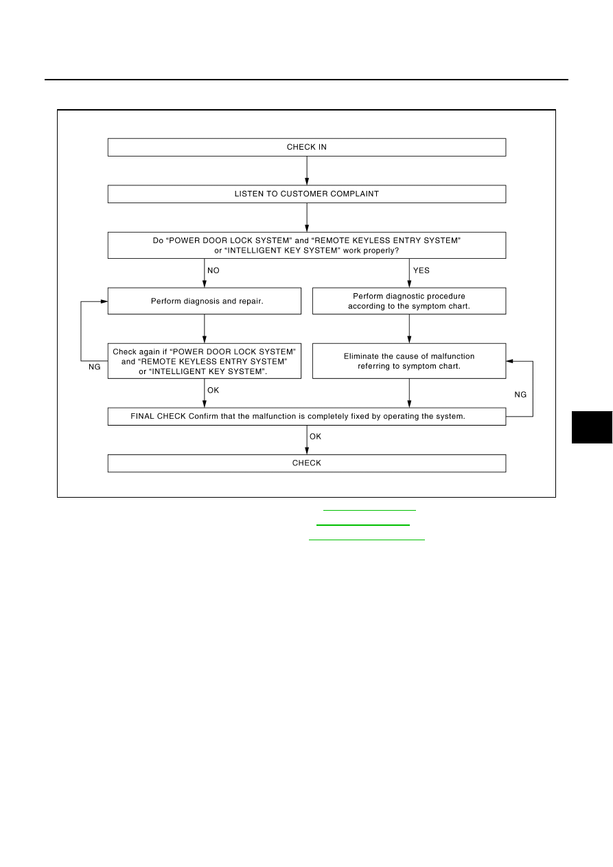
Trouble Diagnosis
AIS001VW
WORK FLOW
●
“POWER DOOR LOCK SYSTEM” Diagnosis; refer to
.
●
“REMOTE CONTROL SYSTEM” Diagnosis; refer to
●
“INTELLIGENT KEY SYSTEM” Diagnosis; refer to
.
PIIA6909E