Nissan Murano Z50 (2005 year). Manual - part 23
NAVIGATION SYSTEM
AV-175
C
D
E
F
G
H
I
J
L
M
A
B
AV
Revision: 2005 August
2005 Murano
Power Supply and Ground Circuit Check for A/C and AV Switch
AKS005LU
1.
CHECK FUSE
Make sure that the following fuses of A/C and AV switch are not blown.
OK or NG
OK
>> GO TO 2.
NG
>> If fuse is blown, be sure to eliminate cause of malfunction before installing new fuse. Refer to
3, "POWER SUPPLY ROUTING CIRCUIT"
.
2.
CHECK POWER SUPPLY CIRCUIT
Check voltage between A/C and AV switch harness connector termi-
nals and ground.
OK or NG
OK
>> GO TO 3.
NG
>> Repair harness or connector.
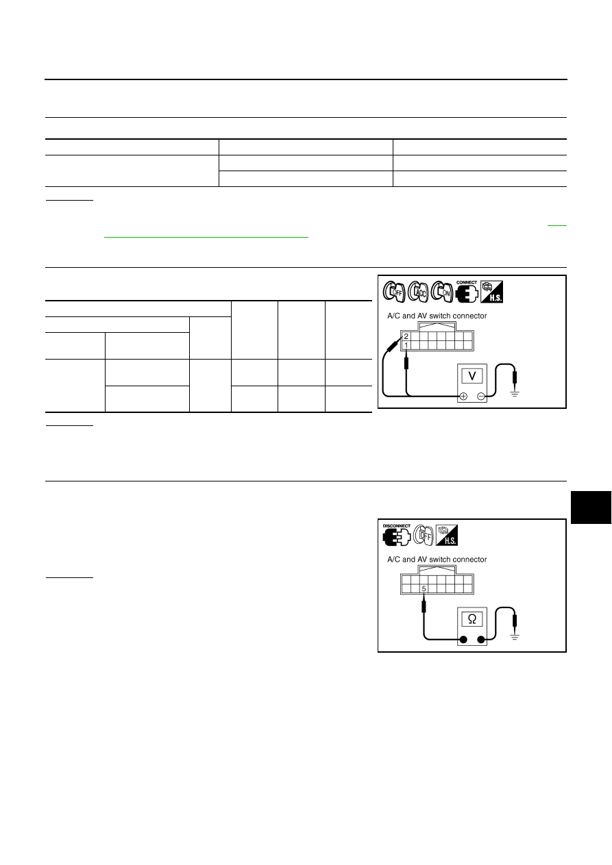
3.
CHECK GROUND CIRCUIT
1.
Turn ignition switch OFF.
2.
Disconnect A/C and AV switch connector.
3.
Check continuity between A/C and AV switch harness connector
M48 terminal 5 (B) and ground.
OK or NG
OK
>> INSPECTION END
NG
>> Repair harness or connector.
Unit
Signal
Fuse No.
A/C and AV switch
Battery power supply
38
ACC power supply
6
Terminals
OFF
ACC
ON
(+)
(–)
Connector
Terminal
(Wire color)
M48
1 (Y)
Ground
Battery
voltage
Battery
voltage
Battery
voltage
2 (P/B)
0 V
Battery
voltage
Battery
voltage
SKIA9396E
5 – Ground
: Continuity should exist.
PKIA2860E