Nissan Murano Z50 (2003 year). Manual - part 183
LAN-542
[CAN]
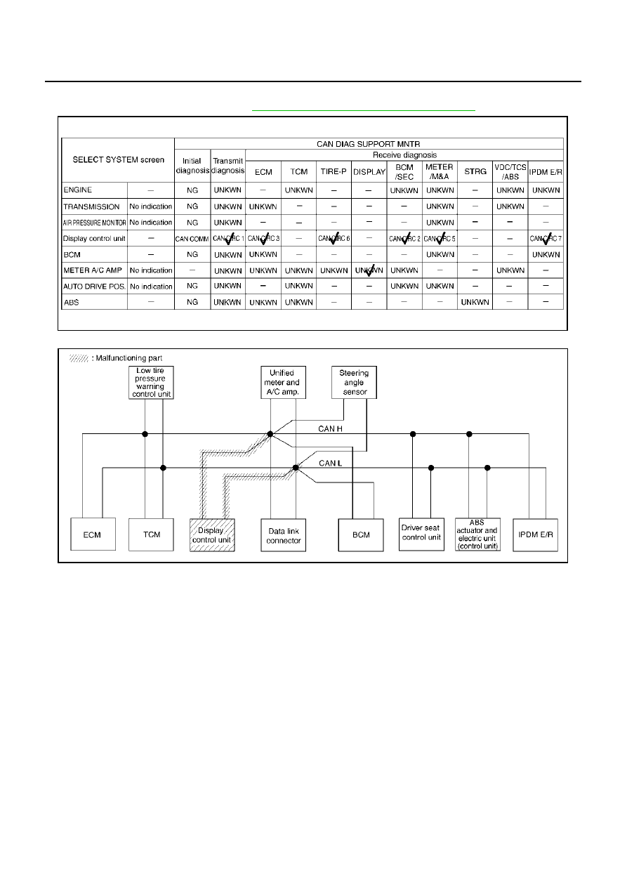
CAN SYSTEM (TYPE 16)
Revision; 2004 April
2003 Murano
Case 7
Check display control unit circuit. Refer to
LAN-554, "Display Control Unit Circuit Check"
PKIB0700E
SKIA5325E
|
|
|
LAN-542 [CAN] CAN SYSTEM (TYPE 16) Revision; 2004 April 2003 Murano Case 7 Check display control unit circuit. Refer to LAN-554, "Display Control Unit Circuit Check" PKIB0700E SKIA5325E |