Nissan Murano Z51 (2008 year). Manual - part 269


  Index      Manuals     Nissan Murano Z51 (2008 year) - Service and Repair Manual


Search            copyright infringement  


Content      ..     267      268      269      270     ..


Nissan Murano Z51 (2008 year). Manual - part 269


MWI

DIAGNOSIS SYSTEM (METER)

MWI-33

< FUNCTION DIAGNOSIS >

C

D

E

F

G

H

I

J

K

L

M

B

A

O

P

DIAGNOSIS SYSTEM (METER)

Diagnosis Description

INFOID:0000000003415506

SELF-DIAGNOSIS MODE

• Information display LCD segment operation can be checked in self-diagnosis mode.
• Meters/gauges can be checked in self-diagnosis mode.

OPERATION PROCEDURE

1.

Turn ignition switch ON, and switch the trip meter to “trip A” or “trip B”.
NOTE:
If the diagnosis function is activated with “trip A” displayed, the mileage on “trip A” is reset to “0000.0”.
(The same way for “trip B”.)

2.

Turn ignition switch OFF.

3.

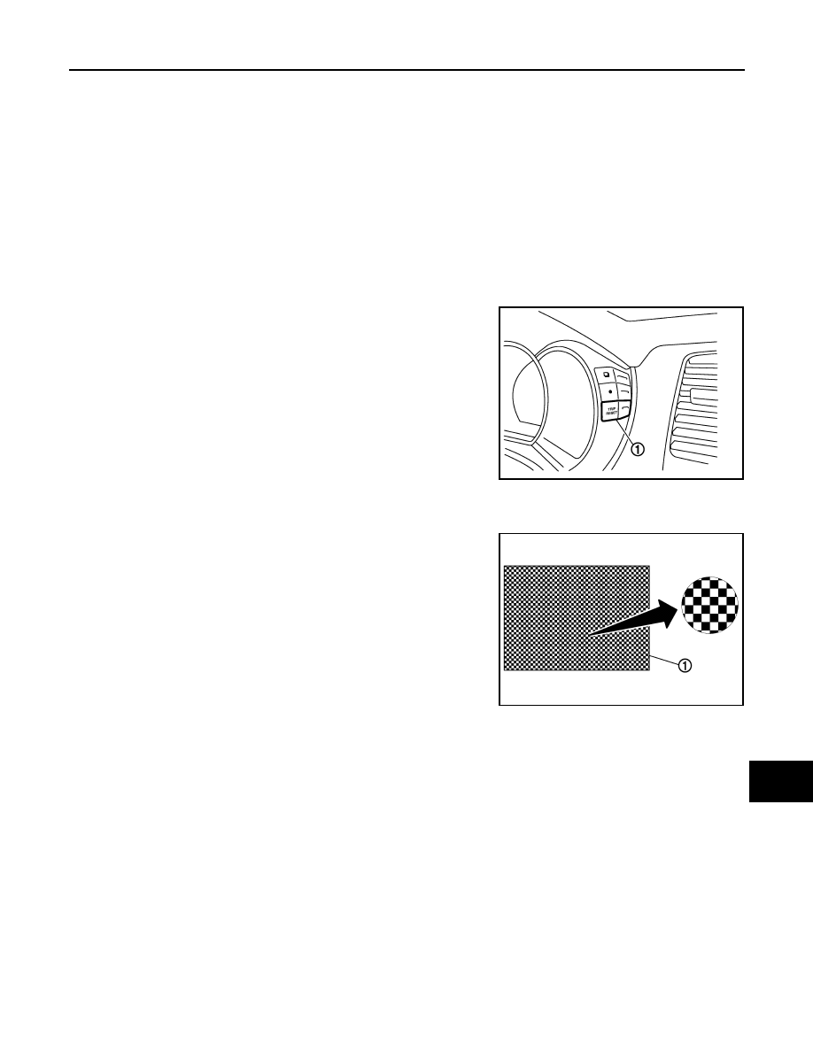
While pressing the trip reset switch (1), turn ignition switch ON
again.

4.

Make sure that the trip meter displays “0000.0”.

5.

Press the trip reset switch at least 3 times. (Within 7 seconds
after the ignition switch is turned ON.)

6.

The unified meter control unit is turned to self-diagnosis mode.
• All the segments on the odo/trip meter and shift position indicator illuminate.
• The segment dots of the information display LCD (1) blink

alternately. 

• Engine coolant temperature gauge and fuel gauge return to

zero, simultaneously.

NOTE:
• Check combination meter power supply and ground circuit when the self-diagnosis mode of the combi-

nation meter does not start. Replace combination meter if abnormal.

• If any of the segments are not displayed, replace combination meter.

JPNIA0743ZZ

JPNIA0766ZZ

Revision: 2008 October

2009 Murano

MWI-34

< FUNCTION DIAGNOSIS >

DIAGNOSIS SYSTEM (METER)

7.

Each meter activates by pressing the trip reset switch.

NOTE:
• If any of the meters or gauges are not activated, replace combination meter.
• The figure is reference.

CONSULT-III Function (METER/M&A)

INFOID:0000000003415507

CONSULT-III APPLICATION ITEMS

CONSULT-III can perform the following diagnosis modes via CAN communication and the combination meter.

SELF DIAG RESULT

Refer to 

MWI-75, "DTC Index"

.

DATA MONITOR

Display Item List

X: Applicable

JPNIA0739ZZ

System

Diagnosis mode

Description

METER/M&A

Self Diagnostic Result

The combination meter checks the conditions and displays memorized errors.

Data Monitor

Displays the combination meter input/output data in real time.

Special function

Lighting history of the warning lamp and indicator lamp can be checked.

Display item [Unit]

MAIN

SIGNALS

Description

SPEED METER
[km/h]

X

Value of vehicle speed signal received from ABS actuator and electric unit (control 
unit) via CAN communication.
NOTE:
655.35 is displayed when the malfunction signal is received.

SPEED OUTPUT
[km/h]

X

Vehicle speed signal value transmitted to other units via CAN communication.
NOTE:
655.35 is displayed when the malfunction signal is received.

ODO OUTPUT
[km/h or mph]

Odometer signal value transmitted to other units via CAN communication.

TACHO METER
[rpm]

X

Value of the engine speed signal received from ECM via CAN communication.
NOTE:
8191.875 is displayed when the malfunction signal is received.

FUEL METER
[L]

X

Fuel level indicated on combination meter.

W TEMP METER
[

°

C] 

X

Value of engine coolant temperature signal is received from ECM via CAN com-
munication. 
NOTE:
215 is displayed when the malfunction signal is input.

Revision: 2008 October

2009 Murano

MWI

DIAGNOSIS SYSTEM (METER)

MWI-35

< FUNCTION DIAGNOSIS >

C

D

E

F

G

H

I

J

K

L

M

B

A

O

P

ABS W/L
[On/Off]

Status of ABS warning lamp detected from ABS warning lamp signal is received 
from ABS actuator and electric unit (control unit) via CAN communication.

VDC/TCS IND
[On/Off]

Status of VDC OFF indicator lamp detected from VDC OFF indicator lamp signal 
is received from ABS actuator and electric unit (control unit) via CAN communica-
tion.

SLIP IND
[On/Off]

Status of SLIP indicator lamp detected from slip indicator lamp signal received 
from ABS actuator and electric unit (control unit) via CAN communication.

BRAKE W/L
[On/Off]

Status of brake warning lamp detected from brake warning lamp signal is received 
from ABS actuator and electric unit (control unit) via CAN communication.
NOTE:
Displays “Off” if the brake warning lamp is illuminated when the valve check starts, 
the parking brake switch is turned ON or the brake fluid level switch is turned ON.

DOOR W/L
[On/Off]

Status of door warning detected from door switch signal received from BCM via 
CAN communication.

HI-BEAM IND
[On/Off]

Status of high beam indicator lamp detected from high beam request signal is re-
ceived from BCM via CAN communication.

TURN IND
[On/Off]

Status of turn indicator lamp detected from turn indicator signal is received from 
BCM via CAN communication.

LIGHT IND
[On/Off]

Status of light indicator lamp detected from position light request signal is received 
from BCM via CAN communication.

OIL W/L
[On/Off]

Status of oil pressure warning lamp detected from oil pressure switch signal is re-
ceived from BCM via CAN communication.

MIL
[On/Off] 

Status of malfunction indicator lamp detected from malfunctioning indicator lamp 
signal is received from ECM via CAN communication.

CRUISE IND
[On/Off]

Status of CRUISE indicator detected from ASCD status signal is received from 
ECM via CAN communication.

O/D OFF IND
[On/Off]

Status of O/D OFF indicator detected from O/D OFF indicator signal is received 
from control device.

4WD W/L
[On/Off]

Status of AWD warning lamp detected from AWD warning lamp signal is received 
from AWD control unit via CAN communication.

4WD LOCK IND
[On/Off]

Status of AWD LOCK warning lamp detected from AWD LOCK warning lamp sig-
nal is received from AWD control unit via CAN communication.

FUEL W/L
[On/Off]

Low-fuel warning lamp status detected by the identified fuel level.

WASHER W/L
[On/Off]

Status of washer warning lamp judged from washer level switch input to combina-
tion meter.

AIR PRES W/L
[On/Off]

Status of low tire pressure warning lamp detected from tire pressure signal is re-
ceived from BCM via CAN communication.

KEY G/W W/L
[On/Off]

Status of key warning lamp (G/Y) detected from key warning signal is received 
from BCM via CAN communication.

LCD
[B&P N, B&P I, ID NG, ROTAT, SFT 
P, INSRT, BATT, NO KY, OUTKY, LK 
WN]

Displays status of Intelligent Key system warning detected from meter display sig-
nal is received from BCM via CAN communication.

SHIFT IND
[P, R, N, D, L]

Status of shift position indicator detected from shift position signal is received from 
TCM via CAN communication.

O/D OFF SW
[On/Off] 

Status of O/D OFF switch.

M RANGE SW
[Off]

This item is displayed, but cannot be monitored.

NM RANGE SW
[Off]

This item is displayed, but cannot be monitored.

Display item [Unit]

MAIN

SIGNALS

Description

Revision: 2008 October

2009 Murano

MWI-36

< FUNCTION DIAGNOSIS >

DIAGNOSIS SYSTEM (METER)

NOTE:

Some items are not available according to vehicle specification.

SPECIAL FUNCTION

Special menu

W/L ON HISTORY

• Stores histories when warning/indicator lamp is turned on.
• “W/L ON HISTORY” indicates the “TIME” when the warning/indicator lamp is turned on.
• The “TIME” above is :
- 0 : The condition that the warning/indicator lamp has been turned on 1 or more times after starting the

engine and waiting for 30 seconds.

- 1 - 39 : The number of times the engine was restarted after the 0 condition.
- NO W/L ON HISTORY : Stores NO (0) turning on history of warning/indicator lamp.
NOTE:
• W/L ON HISTORY is not stored for approximately 30 seconds after the engine starts.
• Brake warning lamp does not store any history when the parking the brake is applied or the brake fluid level

gets low.

AT SFT UP SW
[Off]

This item is displayed, but cannot be monitored.

AT SFT DWN SW
[Off]

This item is displayed, but cannot be monitored.

ST SFT UP SW
[Off]

This item is displayed, but cannot be monitored.

ST SFT DWN SW
[Off]

This item is displayed, but cannot be monitored.

PKB SW
[On/Off]

Status of parking brake switch.

BUCKLE SW
[On/Off]

Status of seat belt buckle switch (driver side).

BRAKE OIL SW
[On/Off]

Status of brake fluid level switch.

DISTANCE
[km]

Value of possible driving distance calculated by combination meter.

A/C AMP CONN
[On/Off]

Status of A/C auto amp. connection recognition signal.

ENTER SW
[On/Off]

Status of 

 (ENTER) switch.

SELECT SW
[On/Off]

Status of 

 (SELECT) switch.

OUTSIDE TEMP
[

°

C or 

°

F]

Ambient air temperature value converted from ambient sensor signal received 
from ambient sensor.
NOTE:
This may not match with the temperature value indicated on the information dis-
play. (Because the information display value is a corrected value from the ambient 
sensor input value.)

FUEL LOW SIG
[On/Off]

Status of fuel level low warning signal to output to AV control unit via CAN com-
munication.

BUZZER 
[On/Off]

X

Buzzer status (in the combination meter) is detected from the buzzer output signal 
received from each unit via CAN communication and the warning output condition 
of the combination meter.

Display item [Unit]

MAIN

SIGNALS

Description

Display item

Description

W/L ON HISTORY

Lighting history of warning lamp and indicator lamp can be checked.

Revision: 2008 October

2009 Murano

MWI

DIAGNOSIS SYSTEM (METER)

MWI-37

< FUNCTION DIAGNOSIS >

C

D

E

F

G

H

I

J

K

L

M

B

A

O

P

Display Item

Display item

Description

ABS W/L

Lighting history of ABS warning lamp.

VDC/TCS IND

Lighting history of VDC OFF indicator lamp.

SLIP IND

Lighting history of SLIP indicator lamp.

BRAKE W/L

Lighting history of brake warning lamp.

DOOR W/L

Lighting history of door warning.

TRUNK/GLAS-H

This item is displayed, but cannot be monitored.

OIL W/L

Lighting history of oil pressure warning lamp.

C-ENG W/L

Lighting history of malfunction indicator lamp.

C-ENG2 W/L

This item is displayed, but cannot be monitored.

CRUISE IND

Lighting history of CRUISE indicator lamp.

SET IND

Lighting history of SET indicator.

CRUISE W/L

This item is displayed, but cannot be monitored.

BA W/L

This item is displayed, but cannot be monitored.

O/D OFF IND 

Lighting history of O/D OFF indicator lamp.

ATC/T-AMT W/L

This item is displayed, but cannot be monitored.

ATF TEMP W/L

This item is displayed, but cannot be monitored.

CVT IND

This item is displayed, but cannot be monitored.

SPORT IND

This item is displayed, but cannot be monitored.

4WD W/L

Lighting history of AWD warning lamp.

FUEL W/L

Lighting history of low fuel level warning.

WASHER W/L

Lighting history of low washer fluid warning

AIR PRES W/L

Lighting history of low tire pressure warning lamp.

KEY G/Y W/L

Lighting history of key warning lamp (green/yellow).

KEY R W/L

Lighting history of key warning lamp (red).

KEY KNOB W/L

This item is displayed, but cannot be monitored.

SYS FAIL W/L

This item is displayed, but cannot be monitored.

SFT POSI W/L

This item is displayed, but cannot be monitored.

HV BAT W/L

This item is displayed, but cannot be monitored.

HEV BRAKE W/L

This item is displayed, but cannot be monitored.

SFT OPER W/L

This item is displayed, but cannot be monitored.

CHAGE W/L

Lighting history of charge warning lamp.

OIL LEV LOW

This item is displayed, but cannot be monitored.

DPF W/L

This item is displayed, but cannot be monitored.

Revision: 2008 October

2009 Murano

MWI-38

< COMPONENT DIAGNOSIS >

U1000 CAN COMM CIRCUIT

COMPONENT DIAGNOSIS

U1000 CAN COMM CIRCUIT

Description

INFOID:0000000003415512

CAN (Controller Area Network) is a serial communication system for real time application. It is an on-vehicle
multiplex communication system with high data communication speed and excellent error detectability. Many
electronic control units are equipped onto vehicles, and each control unit shares information and links with
other control units during operation (not independent). In CAN communication, control units are connected
with two communication lines (CAN-H line, CAN-L line) allowing a high rate of information transmission with
less wiring. Each control unit transmits/receives data but selectively reads required data only.
CAN Communication Signal Chart. Refer to 

LAN-15, "How to Use CAN Communication Signal Chart"

.

DTC Logic

INFOID:0000000003415513

DTC DETECTION LOGIC

Diagnosis Procedure

INFOID:0000000003415514

1.

PERFORM SELF DIAGNOSTIC

1.

Turn ignition switch ON and wait for 2 seconds or more.

2.

Check “Self Diagnostic Result” of “METER/M&A”. 

Is “CAN COMM CIRCUIT” displayed?

YES

>> Refer to 

LAN-16, "Trouble Diagnosis Flow Chart"

.

NO

>> Refer to 

GI-40, "Intermittent Incident"

.

DTC

Display contents of 

CONSULT-III

Diagnostic item is detected when ...

Probable malfunction location

U1000

CAN COMM CIRCUIT

When combination meter is not transmitting or 
receiving CAN communication signal for 2 
seconds or more.

CAN communication system

Revision: 2008 October

2009 Murano

MWI

U1010 CONTROL UNIT (CAN)

MWI-39

< COMPONENT DIAGNOSIS >

C

D

E

F

G

H

I

J

K

L

M

B

A

O

P

U1010 CONTROL UNIT (CAN)

Description

INFOID:0000000003415515

Initial diagnosis of combination meter.

DTC Logic

INFOID:0000000003415516

DTC DETECTION LOGIC

Diagnosis Procedure

INFOID:0000000003415517

1.

REPLACE COMBINATION METER

When DTC “U1010” is detected, replace combination meter.

>> INSPECTION END

DTC

Display contents of CON-

SULT-III

Diagnostic item is detected when ...

Probable malfunction location

U1010

CONTROL UNIT (CAN)

If any malfunction is detected during initial di-
agnosis of combination meter CAN controller

Combination meter

Revision: 2008 October

2009 Murano

MWI-40

< COMPONENT DIAGNOSIS >

B2205 VEHICLE SPEED

B2205 VEHICLE SPEED

Description

INFOID:0000000003415524

Vehicle speed signal is transmitted from ABS actuator and electric unit (control unit) via CAN communication
to combination meter.

DTC Logic

INFOID:0000000003415525

DTC DETECTION LOGIC

Diagnosis Procedure

INFOID:0000000003415526

1.

PERFORM SELF-DIAGNOSIS OF ABS ACTUATOR AND ELECTRIC UNIT (CONTROL UNIT)

Perform “Self Diagnostic Result” of ABS actuator and electric unit (control unit), and repair or replace malfunc-
tioning parts.

>> Refer to 

BRC-29, "CONSULT-III Function"

.

DTC

Display contents of 

CONSULT-III

Diagnostic item is detected when ...

Probable malfunction location

B2205

VEHICLE SPEED

An abnormal vehicle speed signal is input 
from ABS actuator and electric unit (control 
unit) for 2 seconds or more

• Wheel sensor
• ABS actuator and electric unit (control unit)

Revision: 2008 October

2009 Murano

MWI

B2267 ENGINE SPEED

MWI-41

< COMPONENT DIAGNOSIS >

C

D

E

F

G

H

I

J

K

L

M

B

A

O

P

B2267 ENGINE SPEED

Description

INFOID:0000000003415527

The engine speed signal is transmitted from ECM to the combination meter via CAN communication.

DTC Logic

INFOID:0000000003415528

DTC DETECTION LOGIC

Diagnosis Procedure

INFOID:0000000003415529

1.

PERFORM SELF-DIAGNOSIS OF ECM

Perform “Self Diagnostic Result” of ECM, and repair or replace malfunctioning parts.

>> Refer to 

EC-115, "CONSULT-III Function"

.

DTC

Display contents of 

CONSULT-III

Diagnostic item is detected when ...

Probable malfunction location

B2267

ENGINE SPEED

ECM continuously transmits abnormal engine 
speed signals for 2 seconds or more 

• Crankshaft position sensor (POS)
• ECM

Revision: 2008 October

2009 Murano

MWI-42

< COMPONENT DIAGNOSIS >

B2268 WATER TEMP

B2268 WATER TEMP

Description

INFOID:0000000003415530

The engine coolant temperature signal is transmitted from ECM to the combination meter via CAN communi-
cation.

DTC Logic

INFOID:0000000003415531

DTC DETECTION LOGIC

Diagnosis Procedure

INFOID:0000000003415532

1.

PERFORM SELF-DIAGNOSIS OF ECM

Perform “Self Diagnosis Result” of ECM, and repair or replace malfunctioning parts.

>> Refer to 

EC-115, "CONSULT-III Function"

.

DTC

Display contents of 

CONSULT-III

Diagnostic item is detected when ...

Probable malfunction location

B2268

WATER TEMP

ECM continuously transmits abnormal engine 
coolant temperature signals for 60 seconds or 
more 

• Engine coolant temperature sensor
• ECM

Revision: 2008 October

2009 Murano

MWI

POWER SUPPLY AND GROUND CIRCUIT

MWI-43

< COMPONENT DIAGNOSIS >

C

D

E

F

G

H

I

J

K

L

M

B

A

O

P

POWER SUPPLY AND GROUND CIRCUIT

COMBINATION METER

COMBINATION METER : Diagnosis Procedure

INFOID:0000000003415533

1.

CHECK FUSE

Check for blown fuses.

Is the inspection result normal?

YES

>> GO TO 2.

NO

>> Be sure to eliminate cause of malfunction before installing new fuse.

2.

CHECK POWER SUPPLY CIRCUIT

Check voltage between combination meter harness connector terminals and ground.

Is the inspection result normal?

YES

>> GO TO 3.

NO

>> Check harness between combination meter and fuse.

3.

CHECK GROUND CIRCUIT

1.

Turn ignition switch OFF.

2.

Disconnect combination meter connector.

3.

Check continuity between combination meter harness connector terminals and ground.

Is the inspection result normal?

YES

>> INSPECTION END

NO

>> Repair harness or connector.

BCM (BODY CONTROL MODULE)

BCM (BODY CONTROL MODULE) : Diagnosis Procedure

INFOID:0000000003470006

1.

CHECK FUSE AND FUSIBLE LINK

Check that the following fuse and fusible link are not blown.

Power source

Fuse No.

Battery

11

Ignition switch ON or START 

4

Terminals

Ignition switch po-

sition

Voltage

(Approx.)

(+)

(-)

Combination meter

Ground

Connector

Terminal

M34

1

OFF

Battery voltage

2

ON

Terminals

Continuity

(+)

(-)

Combination meter

Ground

Connector

Terminal

M34

3

Existed

23

Revision: 2008 October

2009 Murano

MWI-44

< COMPONENT DIAGNOSIS >

POWER SUPPLY AND GROUND CIRCUIT

Is the fuse fusing?

YES

>> Replace the blown fuse or fusible link after repairing the affected circuit if a fuse or fusible link is

blown.

NO

>> GO TO 2.

2.

CHECK POWER SUPPLY CIRCUIT

1.

Turn ignition switch OFF.

2.

Disconnect BCM connectors.

3.

Check voltage between BCM harness connector and ground.

Is the measurement value normal?

YES

>> GO TO 3.

NO

>> Repair harness or connector.

3.

CHECK GROUND CIRCUIT

Check continuity between BCM harness connector and ground.

Does continuity exist?

YES

>> INSPECTION END

NO

>> Repair harness or connector.

IPDM E/R (INTELLIGENT POWER DISTRIBUTION MODULE ENGINE ROOM)

IPDM E/R (INTELLIGENT POWER DISTRIBUTION MODULE ENGINE ROOM) : Di-
agnosis Procedure

INFOID:0000000003470007

1.

CHECK FUSES AND FUSIBLE LINK

Check that the following IPDM E/R fuses or fusible links are not blown.

Is the fuse fusing?

YES

>> Replace the blown fuse or fusible link after repairing the affected circuit if a fuse or fusible link is

blown.

NO

>> GO TO 2.

2.

CHECK POWER SUPPLY CIRCUIT

1.

Turn the ignition switch OFF.

Signal name

Fuse and fusible link No.

Battery power supply

M

10

Terminals

Voltage

(Approx.)

(+)

(

)

BCM

Ground

Connector

Terminal

M118

1

Battery voltage

M119

11

BCM

Ground

Continuity

Connector

Terminal

M119

13

Existed

Signal name

Fuses and fusible link No.

Battery power supply

E

50

51

Revision: 2008 October

2009 Murano

MWI

POWER SUPPLY AND GROUND CIRCUIT

MWI-45

< COMPONENT DIAGNOSIS >

C

D

E

F

G

H

I

J

K

L

M

B

A

O

P

2.

Disconnect IPDM E/R connector.

3.

Check voltage between IPDM E/R harness connector and the ground.

Is the measurement value normal?

YES

>> GO TO 3.

NO

>> Repair the harness or connector.

3.

CHECK GROUND CIRCUIT

Check continuity between IPDM E/R harness connectors and the ground.

Does continuity exist?

YES

>> INSPECTION END

NO

>> Repair the harness or connector.

Terminals

Voltage

(Approx.)

(+)

(

)

IPDM E/R

Connector

Terminal

Ground

E9

1

Battery voltage

IPDM E/R

Ground

Continuity

Connector

Terminal

E10

12

Existed

E11

41

Revision: 2008 October

2009 Murano

MWI-46

< COMPONENT DIAGNOSIS >

FUEL LEVEL SENSOR SIGNAL CIRCUIT

FUEL LEVEL SENSOR SIGNAL CIRCUIT

Description

INFOID:0000000003415538

The fuel level sensor unit and fuel pump (main) and the fuel level sensor unit (sub) detect the fuel level in the
fuel tank and transmit the fuel gauge signal to the combination meter.

Component Function Check

INFOID:0000000003415539

1.

CHECK COMBINATION METER OUTPUT SIGNAL

Select the “Data Monitor” for the “METER/M&A” and compare the “FUEL METER” monitor value with the fuel
gauge reading on the combination meter.

Does monitor value match fuel gauge reading?

YES

>> INSPECTION END

NO

>> Replace combination meter.

Diagnosis Procedure

INFOID:0000000003415540

1.

CHECK COMBINATION METER INPUT SIGNAL

1.

Turn ignition switch ON.

2.

Check voltage between combination meter harness connector terminal and ground.

Does it match fuel gauge reading?

YES

>> GO TO 2.

NO

>> Replace the combination meter.

2.

CHECK FUEL LEVEL SENSOR CIRCUIT

1.

Turn ignition switch OFF.

2.

Disconnect combination meter connector and fuel level sensor unit (main) connector.

3.

Check continuity between combination meter harness connector terminal and fuel level sensor unit (main)
harness connector terminal.

Fuel gauge pointer

Reference value of data monitor [lit.]

Full

Approx. 77.8

Three quarters

Approx. 63.0

Half

Approx. 42.5

A quarter

Approx. 22.0

Empty

Approx. 7.1

Terminals

Voltage

(Approx.)

(+)

(-)

Combination meter

Ground

Terminal

Connector

M34

34

JPNIA0740ZZ

Revision: 2008 October

2009 Murano

MWI

FUEL LEVEL SENSOR SIGNAL CIRCUIT

MWI-47

< COMPONENT DIAGNOSIS >

C

D

E

F

G

H

I

J

K

L

M

B

A

O

P

4.

Check continuity between combination meter harness connector terminal and ground.

Is the inspection result normal?

YES

>> GO TO 3.

NO

>> Repair harness or connector.

3.

CHECK FUEL LEVEL SENSOR GROUND CIRCUIT

Check continuity between fuel level sensor unit (main) harness connector terminal and combination meter har-
ness connector terminal.

Is the inspection result normal?

YES

>> INSPECTION END

NO

>> Repair harness or connector.

Component Inspection

INFOID:0000000003415541

1.

REMOVE FUEL LEVEL SENSOR UNIT

Remove the fuel level sensor unit. Refer to 

FL-6, "Removal and Installation"

>> GO TO 2.

2.

CHECK FUEL LEVEL SENSOR UNIT AND FUEL PUMP (MAIN)

Check the resistance between fuel level sensor unit and fuel pump (main).

Is the inspection result normal?

YES

>> GO TO 3.

NO

>> Replace fuel level sensor unit and fuel pump (main).

3.

CHECK FUEL LEVEL SENSOR UNIT (SUB)

Terminals

Continuity

(+)

(-)

Combination meter

Fuel level sensor unit (main)

Connector

Terminal

Connector

Terminal

M34

34

B40

2

Existed

Terminals

Continuity

(+)

(-)

Combination meter

Ground

Connector

Terminal

M34

34

Not existed

Terminals

Continuity

(+)

(-)

Fuel level sensor unit (main)

Combination meter

Connector

Terminal

Connector

Terminal

B40

5

M34

24

Existed

Terminals

Condition

Resistance (

)

(Approx.)

Height [mm (in)]

(Approx.)

Fuel level sensor unit 

(main)

5

6

Full (A)

2.5

193 (7.6)

Empty (B)

81.5

15 (0.59)

2

7

0

JPNIA1323ZZ

Revision: 2008 October

2009 Murano

MWI-48

< COMPONENT DIAGNOSIS >

FUEL LEVEL SENSOR SIGNAL CIRCUIT

Inspect the resistance of fuel level sensor unit (sub).

Is the inspection result normal?

YES

>> INSPECTION END

NO

>> Replace fuel level sensor unit (sub).

Terminals

Condi-

tion

Resistance (

)

(Approx.)

Height [mm (in)]

(Approx.)

Fuel level sen-

sor unit (sub)

(+)

(-)

6

7

Full (A)

2.5

198 (7.8)

Empty 

(B)

45.2

10 (0.39)

JPNIA0738ZZ

Revision: 2008 October

2009 Murano


Content      ..     267      268      269      270     ..