Nissan Murano Z51 (2008 year). Manual - part 201
EXL-324
< SYMPTOM DIAGNOSIS >
[HALOGEN TYPE]
EXTERIOR LIGHTING SYSTEM SYMPTOMS
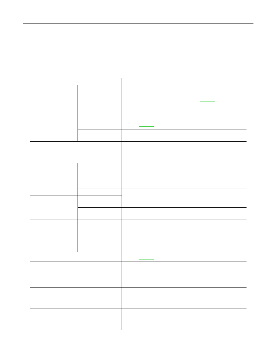
SYMPTOM DIAGNOSIS
EXTERIOR LIGHTING SYSTEM SYMPTOMS
Symptom Table
INFOID:0000000003261469
CAUTION:
Perform the self-diagnosis with CONSULT-III before the symptom diagnosis. Perform the trouble diag-
nosis if any DTC is detected.
Symptom
Possible cause
Inspection item
Headlamp (HI) is not
turned ON.
One side
• Fuse
• Halogen bulb (HI)
• Harness between IPDM E/R
and the headlamp high
• IPDM E/R
Headlamp (HI) circuit
Refer to
Both sides
Symptom diagnosis
“BOTH SIDE HEADLAMPS (HI) ARE NOT TURNED ON”
Refer to
Headlamp (HI) is not
turned OFF.
When ignition switch is
turned ON.
When ignition switch is
turned OFF.
IPDM E/R
—
High beam indicator lamp is not turned ON.
[The headlamp (HI) is turned ON.]
Combination meter
• Combination meter
Data monitor “HI-BEAM IND”
• BCM (HEAD LAMP)
Active test “HEADLAMP”
Headlamp (LO) is not
turned ON.
One side
• Fuse
• Halogen bulb (LO)
• Harness between IPDM E/R
and the headlamp low
• IPDM E/R
Headlamp (LO) circuit
Refer to
Both sides
Symptom diagnosis
“BOTH SIDE HEADLAMPS (LO) ARE NOT TURNED ON”
Refer to
Headlamp (LO) is not
turned OFF.
When ignition switch is
turned ON.
When ignition switch is
turned OFF.
IPDM E/R
—
Front fog lamp is not
turned ON.
One side
• Front fog lamp bulb
• Harness between IPDM E/R
and the front fog lamp
• Front fog lamp
• IPDM E/R
Front fog lamp circuit
Refer to
Both sides
Symptom diagnosis
“BOTH SIDE FRONT FOG LAMPS ARE NOT TURNED ON”
Refer to
Front fog lamp is not turned ON.
Parking lamp is not turned ON.
• Parking lamp bulb
• Harness between IPDM E/R
and the front combination lamp
• Front combination lamp
• IPDM E/R
Parking lamp circuit
Refer to
Front side marker lamp is not turned ON.
• Front side marker lamp bulb
• Harness between IPDM E/R
and the front side marker lamp
• IPDM E/R
Front side marker lamp circuit
Refer to
Parking lamp and front side marker lamp are not
turned ON.
• Fuse
• Harness between IPDM E/R
and the front combination lamp
• IPDM E/R
Parking lamp circuit
Refer to
Revision: 2008 October
2009 Murano