Nissan Murano Z51 (2008 year). Manual - part 174


  Index      Manuals     Nissan Murano Z51 (2008 year) - Service and Repair Manual


Search            copyright infringement  


Content      ..     172      173      174      175     ..


Nissan Murano Z51 (2008 year). Manual - part 174


FUEL INJECTOR AND FUEL TUBE

EM-49

< ON-VEHICLE REPAIR >

C

D

E

F

G

H

I

J

K

L

M

A

EM

N

P

O

• Insert until you hear a “click” sound and actually feel the engagement.
• To avoid misidentification of engagement with a similar sound, be sure to perform the next step.

d.

Pull quick connector by hand holding position. Check it is completely engaged (connected) so that it does
not come out from fuel tube.

e.

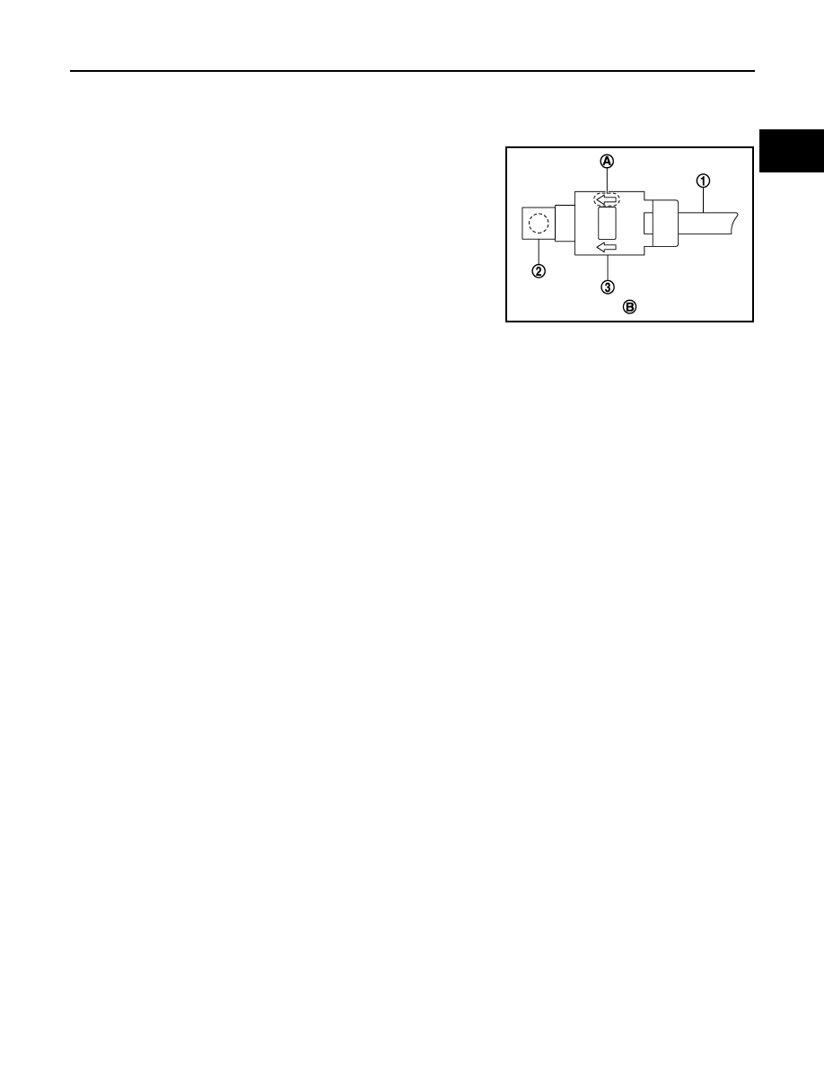
Install quick connector cap (3) to quick connector.

• Install quick connector cap with arrow (A) on surface facing in

direction of quick connector (fuel feed hose side).

CAUTION:

If quick connector cap cannot be installed smoothly, quick
connector may have not been installed correctly. Check
connection again.

f.

Secure fuel feed hose to clamp of quick connector cap.

8.

Install in the reverse order of removal after this step.

Inspection

INFOID:0000000003304115

INSPECTION AFTER INSTALLATION

Check on Fuel Leakage

1.

Turn ignition switch “ON” (with the engine stopped). With fuel pressure applied to fuel piping, check there
are no fuel leakage at connection points.
NOTE:
Use mirrors for checking at points out of clear sight.

2.

Start the engine. With engine speed increased, check again that there are no fuel leakage at connection
points.

CAUTION:

Never touch the engine immediately after stopped, as the engine becomes extremely hot.

1

: Fuel feed hose

2

: Fuel tube

B

: Upper view

JPBIA0039ZZ

Revision: 2008 October

2009 Murano

EM-50

< ON-VEHICLE REPAIR >

IGNITION COIL, SPARK PLUG AND ROCKER COVER

IGNITION COIL, SPARK PLUG AND ROCKER COVER

Exploded View

INFOID:0000000003304120

Removal and Installation

INFOID:0000000003304121

REMOVAL

1.

Remove the following parts:
• Engine cover: Refer to 

EM-25, "Exploded View"

.

• Air cleaner cases (upper and lower) and air duct assembly: Refer to 

EM-27, "Exploded View"

.

• Intake manifold collector: Refer to 

EM-29, "Exploded View"

.

2.

Disconnect PCV hose from rocker cover.

1.

Ignition coil

2.

Spark plug

3.

PCV hose

4.

Clamp

5.

PCV valve

6.

O-ring

7.

Rocker cover (bank 1)

8.

PCV hose

9.

Rocker cover gasket (bank 1)

10.

O-ring

11.

Camshaft position sensor (PHASE) 
(bank 1)

12. Oil filler cap

13.

Rocker cover (bank 2)

14.

Rocker cover gasket (bank 2)

15.

Camshaft position sensor (PHASE) 
(bank 2)

16.

PCV hose

17.

Clamp

A.

To intake manifold collector

B.

Refer to 

EM-50

C.

Camshaft bracket side

D.

To air duct assembly

Refer to 

GI-4, "Components"

 for symbols in the figure.

JPBIA1637GB

Revision: 2008 October

2009 Murano

IGNITION COIL, SPARK PLUG AND ROCKER COVER

EM-51

< ON-VEHICLE REPAIR >

C

D

E

F

G

H

I

J

K

L

M

A

EM

N

P

O

3.

Remove camshaft position sensor (PHASE) (bank 1 and bank
2).

CAUTION:

• Handle carefully to avoid dropping and shocks.
• Never disassemble
• Never allow metal powder to adhere to magnetic part at

sensor tip. 

• Never place sensors in a location where they are exposed

to magnetism.

4.

Remove PCV valve and O-ring from rocker cover, if necessary.

5.

Remove oil filler cap from rocker cover, if necessary. 

6.

Remove ignition coil.

CAUTION:

Never shock ignition coil.

7.

Remove harness clips on the rocker cover.

8.

Loosen bolts in the reverse order shown in the figure.

9.

Remove rocker cover gasket from rocker cover.

10. Use scraper to remove all traces of liquid gasket from cylinder head and camshaft bracket (No. 1).

CAUTION:

Never scratch or damage the mating surface when cleaning off old liquid gasket.

INSTALLATION

A

: Keep off any magnetic materials

: Engine front

JPBIA0454ZZ

JPBIA1634ZZ

Revision: 2008 October

2009 Murano

EM-52

< ON-VEHICLE REPAIR >

IGNITION COIL, SPARK PLUG AND ROCKER COVER

1.

Apply liquid gasket to the position shown in the figure with the
following procedure:

Use Genuine RTV silicone sealant or equivalent. Refer to

GI-

17, "Recommended Chemical Products and Sealants"

.

a.

Refer to figure (E) to apply liquid gasket to joint part of camshaft
bracket (No. 1) (1) and cylinder head.

b.

Refer to figure (H) to apply liquid gasket in 90 degrees to figure.

2.

Install rocker cover gasket to rocker cover.

3.

Install rocker cover.
• Check if rocker cover gasket is not dropped from the installation groove of rocker cover. 

4.

Tighten bolts in two steps separately in numerical order as
shown in the figure.

5.

Install in the reverse order of removal after this step. 

A

: Liquid gasket application point

F

:  View  F

I

: End surface of camshaft bracket (No. 1)

b

: 4 mm (0.16 in)

c

φ

2.5 - 3.5 mm (0.098 - 0.138 in)

d

: 5 mm (0.20 in)

g

: 10 mm (0.39 in)

: Engine front

JPBIA0274ZZ

: Engine front

 1st step

: 1.96 N·m (0.20 kg-m, 17 in-lb)

 2nd step

: 8.33 N·m (0.85 kg-m, 74 in-lb)

JPBIA1634ZZ

Revision: 2008 October

2009 Murano

TIMING CHAIN

EM-53

< ON-VEHICLE REPAIR >

C

D

E

F

G

H

I

J

K

L

M

A

EM

N

P

O

TIMING CHAIN

Exploded View

INFOID:0000000003685476

1.

Timing chain tensioner (secondary)
(bank 2)

2.

Internal chain guide

3.

Timing chain tensioner (secondary)
(bank 1)

4.

Oil temperature sensor

5.

Camshaft sprocket (EXH)

6.

O-ring

7.

Timing chain (secondary)

8.

Timing chain (primary)

9.

Camshaft sprocket (INT)

10. Slack guide

11. Timing chain tensioner (primary)

12.

Crankshaft sprocket

13. Rear timing chain case

14. Tension guide

15.

O-ring

16. O-ring

17. O-ring

18.

Front timing chain case

JPBIA2471GB

Revision: 2008 October

2009 Murano

EM-54

< ON-VEHICLE REPAIR >

TIMING CHAIN

Removal and Installation

INFOID:0000000003685475

REMOVAL

1.

Drain engine oil. Refer to 

LU-8, "Draining"

.

2.

Drain engine coolant from inside engine. Refer to 

EM-86, "Setting"

.

3.

Remove intake manifold collector. Refer to 

EM-29, "Exploded View"

.

4.

Remove rocker covers (bank 1 and bank 2). Refer to 

EM-50, "Exploded View"

.

5.

Remove oil pans (lower and upper) and oil strainer. Refer to 

EM-39, "Exploded View"

.

6.

Remove drive belt, idler pulleys and bracket. Refer to 

EM-13, "Removal and Installation"

 and 

EM-26,

"Exploded View"

.

7.

Remove power steering oil pump with piping connected, and temporarily secure it to aside. Refer to 

ST-

36, "Exploded View"

.

8.

Separate engine harness removing their brackets from front timing chain case.

9.

Remove valve timing control covers.
• Loosen mounting bolts in the reverse order as shown in the

figure.

CAUTION:

Shaft is internally jointed with camshaft sprocket (INT) cen-
ter hole. When removing, keep it horizontal until it is com-
pletely disconnected.

10. Obtain No. 1 cylinder at TDC of its compression stroke as follows:

a.

Rotate crankshaft pulley clockwise to align timing mark (grooved
line without color) (

) with timing indicator.

19.

Valve timing control cover gasket 
(bank 1)

20. Valve timing control cover (bank 1) 21.

Intake valve timing control solenoid valve 
(bank 1)

22. Seal ring

23. Water pump cover

24.

Front oil seal

25. Crankshaft pulley

26. Crankshaft pulley bolt

27.

Intake valve timing control solenoid valve 
(bank 2)

28. Valve timing control cover (bank 2)

29.

Valve timing control cover gasket 
(bank 2)

A.

Refer to 

EM-90

B.

Refer to 

EM-54

Refer to 

GI-4, "Components"

 for symbols in the figure.

A

:  Bank  1

B

:  Bank  2

C

: Dowel pin hole

JPBIA1639ZZ

SEM727G

Revision: 2008 October

2009 Murano

TIMING CHAIN

EM-55

< ON-VEHICLE REPAIR >

C

D

E

F

G

H

I

J

K

L

M

A

EM

N

P

O

b.

Check that intake and exhaust cam noses on No. 1 cylinder
(engine front side of bank 1) are located as shown in the figure.

• If not, turn crankshaft one revolution (360 degrees) and align

as shown in the figure.

11. Remove crankshaft pulley as follows:
a.

Fix crankshaft with the pulley holder (commercial service tool)
(A).

b.

Loosen crankshaft pulley bolt and locate bolt seating surface at
10 mm (0.39 in) from its original position.

CAUTION:

Never remove crankshaft pulley bolt as it will be used as a
supporting point for suitable puller.

c.

Place suitable puller tab on holes of crankshaft pulley, and pull
crankshaft pulley through.

CAUTION:

Never put suitable puller tab on crankshaft pulley periphery,
as this will damage internal damper.

12. Remove front timing chain case as follows:
a.

Loosen mounting bolts in the reverse order as shown in the fig-
ure.

: Engine front

JPBIA0044ZZ

1

: Crankshaft pulley

PBIC3961E

SEM915E

JPBIA1640ZZ

Revision: 2008 October

2009 Murano

EM-56

< ON-VEHICLE REPAIR >

TIMING CHAIN

b.

Insert a suitable tool (A) into the notch at the top of front timing
chain case as shown in the figure.

c.

Pry off case by moving the tool as shown.
• Use the seal cutter [SST: KV10111100 (J-37228)] to cut liquid

gasket for removal. 

CAUTION:

• Never use screwdrivers or something similar.
• After removal, handle front timing chain case carefully so

it does not tilt, cant, or warp under a load.

13. Remove water pump cover from front timing chain case. 

• Use the seal cutter [SST: KV10111100 (J-37228)] to cut liquid gasket for removal. 

14. Remove front oil seal from front timing chain case using a suit-

able tool.
• Use a screwdriver for removal.

CAUTION:

Be careful not to damage front timing chain case.

15. Remove O-ring (1) from rear timing chain case.

16. Remove timing chain tensioner (primary) as follows:

a.

Remove lower mounting bolt (1).

b.

Loosen upper mounting bolt (2) slowly, and then turn timing
chain tensioner (primary) (3) on the mounting bolt so that
plunger (4) is fully expanded.
NOTE:
Even if plunger is fully expanded, it is not dropped from the body
of timing chain tensioner (primary).

c.

Remove upper mounting bolt, and then remove timing chain ten-
sioner (primary).

JPBIA0048ZZ

EMQ0032D

A

:  Bank  1

B

:  Bank  2

JPBIA1111ZZ

JPBIA0085ZZ

Revision: 2008 October

2009 Murano

TIMING CHAIN

EM-57

< ON-VEHICLE REPAIR >

C

D

E

F

G

H

I

J

K

L

M

A

EM

N

P

O

17. Remove internal chain guide, tension guide and slack guide.

NOTE:
Tension guide can be removed after removing timing chain (pri-
mary).

18. Remove timing chain (primary) and crankshaft sprocket.

CAUTION:

After removing timing chain (primary), never turn crankshaft and camshaft separately, or valves
will strike the piston heads.

19. Remove timing chain (secondary) and camshaft sprockets as follows:

a.

Attach a suitable stopper pin (B) to the bank 1 (A) and bank 2
(C) timing chain tensioners (secondary) (1).
NOTE:
• Use approximately 0.5 mm (0.02 in) dia. hard metal pin as a

stopper pin.

• For removal of timing chain tensioner (secondary), refer to

EM-94, "Exploded View"

. [Removing camshaft bracket (No. 1)

is required.]

b.

Remove camshaft sprockets (INT and EXH) mounting bolts.
• Secure the hexagonal portion of camshaft using a wrench to

loosen mounting bolts.

CAUTION:

Never loosen mounting bolts with securing anything
other than the camshaft hexagonal portion or with ten-
sioning the timing chain.

c.

Remove timing chain (secondary) together with camshaft sprockets.
• Turn camshaft slightly to secure slackness of timing chain on timing chain tensioner (secondary) side.

PBIC2266E

JPBIA1727ZZ

KBIA1698J

Revision: 2008 October

2009 Murano

EM-58

< ON-VEHICLE REPAIR >

TIMING CHAIN

• Insert 0.5 mm (0.020 in) thick metal or resin plate between tim-

ing chain and timing chain tensioner plunger (guide) (E).
Remove timing chain (secondary) (2) together with camshaft
sprockets with timing chain loose from guide groove.

CAUTION:

Be careful of plunger coming-off when removing timing chain (secondary). This is because
plunger of timing chain tensioner (secondary) moves during operation, leading to coming-off of
fixed stopper pin. 
NOTE:
• Camshaft sprocket (INT) is two-for-one structure of sprockets for timing chain (primary) and for timing

chain (secondary).

• Figure is shown as an example of bank 1.

• When handling camshaft sprocket (INT), be careful of the fol-

lowing caution:

CAUTION:

• Handle carefully to avoid any shock to camshaft

sprocket.

• Never disassemble. [Never loosen bolts (A) as shown in

the figure].

20. Remove timing chain tensioners (secondary) from cylinder head as follows, if necessary.

• Remove timing chain tensioners (secondary) with a stopper pin attached.

21. Use a scraper to remove all traces of old liquid gasket from front

timing chain case, and opposite mating surfaces.

• Remove old liquid gasket from bolt hole (B) and thread.

1

: Timing chain tensioner (secondary)

A

:  Bank  1

B

:  View  B

C

: Stopper pin

D

:  Plate

F

: Timing chain tensioner (body)

JPBIA2527ZZ

PBIC2980E

SEM737G

A

: Remove sticking old liquid gasket 

JPBIA0051ZZ

Revision: 2008 October

2009 Murano

TIMING CHAIN

EM-59

< ON-VEHICLE REPAIR >

C

D

E

F

G

H

I

J

K

L

M

A

EM

N

P

O

22. Use a scraper to remove all traces of old liquid gasket from

water pump cover.

INSTALLATION

NOTE:
The below figure shows the relationship between the mating mark on each timing chain and that on the corre-
sponding sprocket, with the components installed.

1.

Install timing chain tensioners (secondary) to cylinder head as follows if removed. Refer to 

EM-94,

"Exploded View"

.

• Install timing chain tensioners (secondary) with a stopper pin attached and new O-ring.

SEM926E

1.

Internal chain guide

2.

Camshaft sprocket (INT)

3.

Timing chain (secondary)

4.

Camshaft sprocket (EXH)

5.

Timing chain tensioner (primary)

6.

Slack guide

7.

Timing chain (primary)

8.

Crankshaft sprocket

9.

Water pump

10. Tension guide

11.

Timing chain tensioner (secondary)

12. Crankshaft key

A.

Mating mark

B.

Mating mark (pink link)

C.

Mating mark (punched)

D.

Mating mark (orange)

E.

Mating mark (notched)

JPBIA1716GB

Revision: 2008 October

2009 Murano

EM-60

< ON-VEHICLE REPAIR >

TIMING CHAIN

2.

Check that dowel pin (A) and crankshaft key (1) are located as
shown in the figure. (No. 1 cylinder at compression TDC)
NOTE:
Though camshaft does not stop at the position as shown in the
figure, for the placement of cam nose, it is generally accepted
camshaft is placed for the same direction of the figure.

CAUTION:

Hole on small dia. side must be used for intake side dowel pin hole. Never misidentify (ignore big
dia. side).

3.

Install timing chain (secondary) and camshaft sprockets (INT and EXH) as follows:

CAUTION:

Mating marks between timing chain and sprockets slip easily. Confirm all mating mark positions
repeatedly during the installation process.

a.

Push plunger of timing chain tensioner (secondary) and keep it
pressed in with stopper pin (A).

b.

Install timing chain (secondary) (1) and camshaft sprockets (INT
and EXH).

NOTE:
Figure shows bank 1 (rear view).
• Align the mating marks on timing chain (secondary) (orange

link) with the ones on camshaft sprockets (INT and EXH)
(punched), and install them.
NOTE:
• Mating marks for camshaft sprocket (INT) are on the back

side of camshaft sprocket (secondary).

• There are two types of mating mark, circle and oval types.

They should be used for the bank 1 and bank 2, respectively.

• Align dowel pin on camshafts with the groove or hole on sprockets, and install them.

Camshaft dowel pin

: At cylinder head upper face side in each bank

Crankshaft key

: At cylinder head side of bank 1

JPBIA0094ZZ

JPBIA0095ZZ

A

: Camshaft sprocket (INT) back face

B

: Orange link

C

: Mating mark (Circle)

D

: Camshaft sprocket (EXH) back face

E

: Mating mark (2 circle on front face)

F

: Dowel pin groove

G

: Mating mark (2 ovals on front face)

H

: Mating mark (Oval)

I

: Dowel pin hole

Bank 1

: Use circle type.

Bank 2

: Use oval type.

JPBIA1726ZZ

Revision: 2008 October

2009 Murano

TIMING CHAIN

EM-61

< ON-VEHICLE REPAIR >

C

D

E

F

G

H

I

J

K

L

M

A

EM

N

P

O

• On the intake side, align dowel pin on the camshaft front end with dowel pin hole on the back side of

camshaft sprocket, and install them.

• On the exhaust side, align dowel pin on camshaft front end with dowel pin groove on camshaft sprocket,

and install them.

• In case that positions of each mating mark and each dowel pin are not fit on mating parts, make fine

adjustment to the position holding the hexagonal portion on camshaft with wrench or equivalent.

• Mounting bolts for camshaft sprockets must be tightened in the next step. Tightening them by hand is

enough to prevent the dislocation of dowel pins.

• It may be difficult to visually check the dislocation of mating

marks during and after installation. To make the matching eas-
ier, make a mating mark (A) on the top of sprocket teeth and
its extended line in advance with paint.

c.

After confirming the mating marks are aligned, tighten camshaft sprocket mounting bolts.
• Secure camshaft using wrench at the hexagonal portion to

tighten mounting bolts.

d.

Pull stopper pins (B) out from timing chain tensioners (second-
ary) (1).

4.

Install tension guide.

5.

Install timing chain (primary) as follows:

a.

Install crankshaft sprocket (1).

• Check the mating marks on crankshaft sprocket face the front

of the engine.

b.

Install timing chain (primary).

B

: Mating mark (orange link)

JPBIA2260ZZ

KBIA1698J

A

:  Bank  1

C

:  Bank  2

JPBIA1727ZZ

A

: Crankshaft side

B

: Engine front

C

: Mating mark (front side)

JPBIA0273ZZ

Revision: 2008 October

2009 Murano

EM-62

< ON-VEHICLE REPAIR >

TIMING CHAIN

• Install timing chain (primary) so the mating mark (punched) (B)

on camshaft sprocket (INT) (1) is aligned with the pink link (A)
on timing chain, while the mating mark (notched) (C) on crank-
shaft sprocket (2) is aligned with the orange link (D) on timing
chain, as shown in the figure.

• When it is difficult to align mating marks of timing chain (pri-

mary) with each sprocket, gradually turn camshaft using
wrench on the hexagonal portion to align it with the mating
marks.

• During alignment, be careful to prevent dislocation of mating

mark alignments of timing chains (secondary).

6.

Install internal chain guide (1) and slack guide (2).

CAUTION:

Never over tighten slack guide mounting bolt (2). It is nor-
mal for a gap (A) to exist under the bolt seat when mounting
bolt is tightened to specification.

3

:  Water  pump

JPBIA1601ZZ

3

: Tension guide

JPBIA1104ZZ

1

: Slack guide

3

: Cylinder block

JPBIA0117ZZ

Revision: 2008 October

2009 Murano

TIMING CHAIN

EM-63

< ON-VEHICLE REPAIR >

C

D

E

F

G

H

I

J

K

L

M

A

EM

N

P

O

7.

Install the timing chain tensioner (primary) with the following procedure:

a.

Pull plunger stopper tab (A) up (or turn lever downward) so as to
remove plunger stopper tab from the ratchet of plunger (D).
NOTE:
Plunger stopper tab and lever (C) are synchronized.

b.

Push plunger into the inside of tensioner body.

c.

Hold plunger in the fully compressed position by engaging
plunger stopper tab with the tip of ratchet.

d.

To secure lever, insert stopper pin (E) through hole of lever into
tensioner body hole (B).
• The lever parts and the tab are synchronized. Therefore, the

plunger will be secured under this condition.

NOTE:
Figure shows the example of 1.2 mm (0.047 in) diameter thin screwdriver being used as the stopper pin.

e.

Install timing chain tensioner (primary) (1).
• Remove any dirt and foreign materials completely from the

back and the mounting surfaces of timing chain tensioner (pri-
mary).

f.

Pull out stopper pin (A) after installing, and then release plunger.

8.

Check again that the mating marks on each sprocket and each timing chain have not slipped out of align-
ment.

9.

Install new O-rings (1) on rear timing chain case.

10. Install new front oil seal on front timing chain case.

• Apply new engine oil to both oil seal lip and dust seal lip.
• Install it so that each seal lip is oriented as shown in the figure. 

JPBIA0118ZZ

JPBIA0119ZZ

A

:  Bank  1

B

:  Bank  2

JPBIA1111ZZ

A

:  Oil  seal  lip

B

: Dust seal lip

: Engine inside

: Engine outside

JPBIA0054ZZ

Revision: 2008 October

2009 Murano

EM-64

< ON-VEHICLE REPAIR >

TIMING CHAIN

• Using a suitable drift [outer diameter: 60 mm (2.36 in)], press-

fit oil seal until it becomes flush with front timing chain case
end face.

• Check the garter spring is in position and seal lip is not

inverted.

11. Install water pump cover to front timing chain case.

• Apply a continuous bead of liquid gasket with the tube presser

(commercial service tool) to water pump cover (1) as shown in
the figure.

Use Genuine RTV Silicone Sealant or equivalent. Refer to

GI-17, "Recommended Chemical Products and Sealants"

.

12. Install front timing chain case as follows:

a.

Apply a continuous bead of liquid gasket with the tube presser
(commercial service tool) to front timing chain case back side as
shown in the figure.

Use Genuine RTV Silicone Sealant or equivalent. Refer to

GI-17, "Recommended Chemical Products and Sealants"

.

b.

Install front timing chain case as to fit its dowel pin hole together dowel pin on rear timing chain case.

PBIC0790E

a : 

φ

2.3 - 3.3 mm (0.091 - 0.130 in)

JPBIA1722ZZ

D

:  Bolt  hole

E

: Protrusion

f

φ

2.6 - 3.6 mm (0.102 - 0.142 in)

JPBIA2472ZZ

Revision: 2008 October

2009 Murano


Content      ..     172      173      174      175     ..