Nissan Murano Z51 (2008 year). Manual - part 84


  Index      Manuals     Nissan Murano Z51 (2008 year) - Service and Repair Manual


Search            copyright infringement  


Content      ..     82      83      84      85     ..


Nissan Murano Z51 (2008 year). Manual - part 84


CHG

B TERMINAL CIRCUIT

CHG-9

< COMPONENT DIAGNOSIS >

C

D

E

F

G

H

I

J

K

L

B

A

O

P

N

COMPONENT DIAGNOSIS

B TERMINAL CIRCUIT

Description

INFOID:0000000003412942

“B” terminal circuit supplies power to charge the battery and to operate the vehicle’s electrical system.

Diagnosis Procedure

INFOID:0000000003412943

1.

CHECK “B” TERMINAL CONNECTION

1.

Turn ignition switch OFF.

2.

Check if “B” terminal is clean and tight.

Is the inspection result normal?

YES

>> GO TO 2.

NO

>> Repair “B” terminal connection. Confirm repair by performing complete Starting/Charging system

test. Refer to Technical Service Bulletin.

2.

CHECK “B” TERMINAL CIRCUIT

Check voltage between alternator “B” terminal and ground.

Is the inspection result normal?

YES

>> GO TO 3.

NO

>> Check harness for open between alternator and fusible link.

3.

CHECK “B” TERMINAL CONNECTION (VOLTAGE DROP TEST)

1.

Start engine, then engine running at idle and warm.

2.

Check voltage between battery positive terminal and alternator “B” terminal.

Is the inspection result normal?

YES

>> “B” terminal circuit is normal. Refer to 

CHG-2, "Work Flow"

.

NO

>> Check harness between battery and alternator for poor continuity.
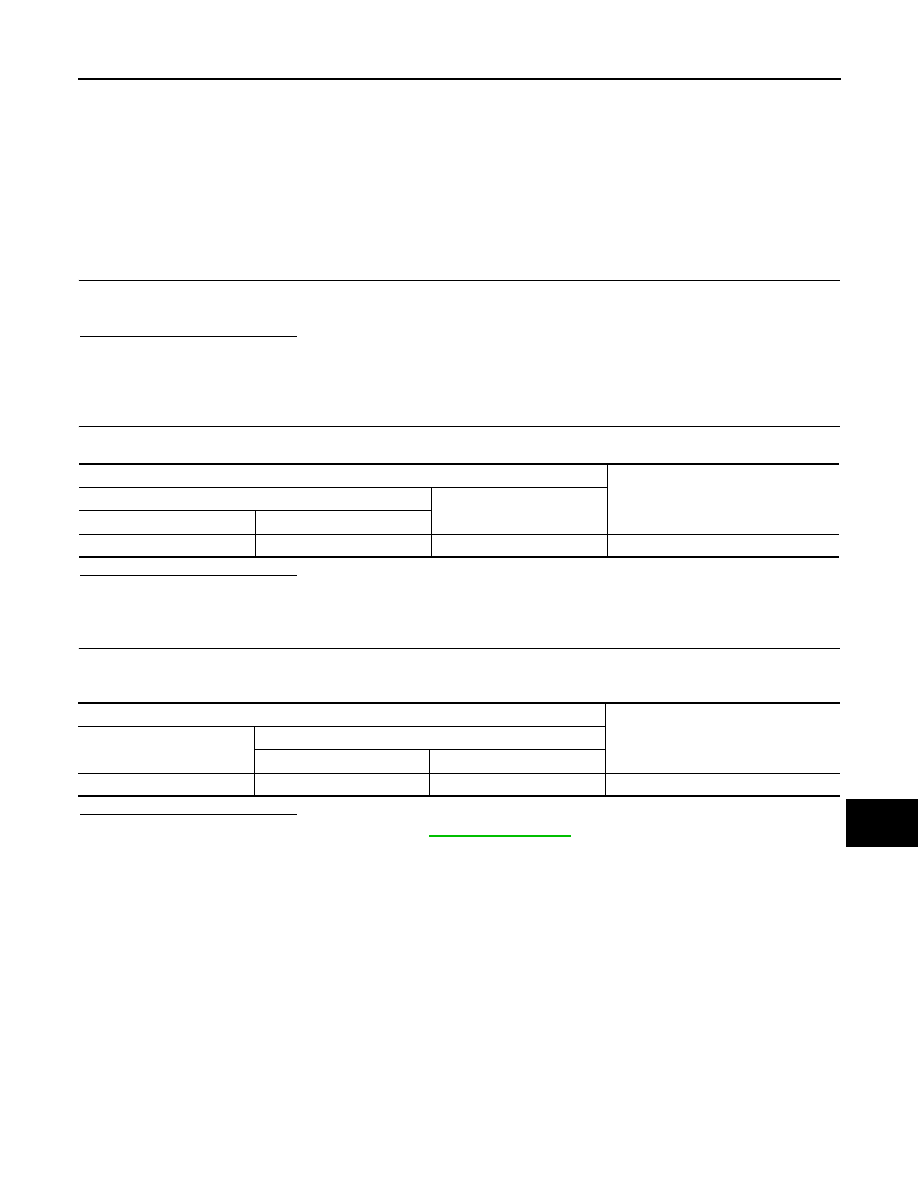
Terminals

Voltage (Approx.)

(+)

(–)

Alternator “B” terminal

Terminal

F59

1

Ground

Battery voltage

Terminals

Voltage (Approx.)

(+)

(–)

Alternator “B” terminal

Terminal

Battery positive terminal

F59

Less than 0.2 V

Revision: 2008 October

2009 Murano

CHG-10

< COMPONENT DIAGNOSIS >

L TERMINAL CIRCUIT (OPEN)

L TERMINAL CIRCUIT (OPEN)

Description

INFOID:0000000003412944

The “L” terminal circuit controls the charge warning lamp. The charge warning lamp illuminates when the igni-
tion switch is set to ON or START. When the alternator is providing sufficient voltage with the engine running,
the charge warning lamp will go off. If the charge warning lamp illuminates with the engine running, a malfunc-
tion is indicated.

Diagnosis Procedure

INFOID:0000000003412945

1.

CHECK “L” TERMINAL CONNECTION

1.

Turn ignition switch OFF.

2.

Check if “L” terminal is clean and tight.

Is the inspection result normal?

YES

>> GO TO 2.

NO

>> Repair “L” terminal connection. Confirm repair by performing complete Starting/Charging system

test. Refer to Technical Service Bulletin.

2.

CHECK “L” TERMINAL CIRCUIT (OPEN)

1.

Disconnect alternator connector.

2.

Apply ground to alternator harness connector terminal.

3.

Check condition of the charge warning lamp with the ignition switch in the ON position.

Does it illuminate?

YES

>> “L” terminal circuit is normal. Refer to 

CHG-2, "Work Flow"

.

NO

>> GO TO 3.

3.

CHECK HARNESS CONTINUITY (OPEN CIRCUIT)

1.

Disconnect the battery cable from the negative terminal.

2.

Disconnect the combination meter connector.

3.

Check continuity between alternator harness connector and combination meter harness connector.

Is the inspection result normal?

YES

>> GO TO 4.

NO

>> Repair the harness or connector.

4.

CHECK HARNESS CONTINUITY (OPEN CIRCUIT)

Check continuity between combination meter harness connector and fuse block.

Is the inspection result normal?

YES

>> GO TO 5.

NO

>> Repair the harness.

5.

CHECK POWER SUPPLY CIRCUIT

1.

Connect the battery cable to the negative terminal.

Alternator harness connector

Terminal

Ground

Condition

Ignition switch position

Charge warning lamp

F60

3

ON

 illuminate

Alternator harness connector

Combination meter harness connector

Continuity

Connector No.

Terminal No.

Connector No.

Terminal No.

F60

3

M34

25

Existed

Combination meter harness connector

Fuse block

Continuity

Connector No.

Terminal No.

Connector No.

Terminal No.

M34

2

M3

12C

Existed

Revision: 2008 October

2009 Murano

CHG

L TERMINAL CIRCUIT (OPEN)

CHG-11

< COMPONENT DIAGNOSIS >

C

D

E

F

G

H

I

J

K

L

B

A

O

P

N

2.

Check voltage between combination meter harness connector and ground.

Is the inspection result normal?

YES

>> Replace combination meter.

NO

>> Inspect the power supply circuit. Refer to 

PG-59, "Wiring Diagram - IGNITION POWER SUPPLY -

"

.

Terminals

Condition

Voltage (Approx.)

(+)

(–)

Combination meter 

harness connector

Terminal

M34

2

Ground

When the ignition switch is in 

ON position

Battery voltage

Revision: 2008 October

2009 Murano

CHG-12

< COMPONENT DIAGNOSIS >

L TERMINAL CIRCUIT (SHORT)

L TERMINAL CIRCUIT (SHORT)

Description

INFOID:0000000003412946

The “L” terminal circuit controls the charge warning lamp. The charge warning lamp illuminates when the igni-
tion switch is set to ON or START. When the alternator is providing sufficient voltage with the engine running,
the charge warning lamp will go off. If the charge warning lamp illuminates with the engine running, a malfunc-
tion is indicated.

Diagnosis Procedure

INFOID:0000000003412947

1.

CHECK “L” TERMINAL CIRCUIT (SHORT)

1.

Turn ignition switch OFF.

2.

Disconnect alternator connector.

3.

Turn ignition switch ON.

Does charge warning lamp illuminate?

YES

>> GO TO 2.

NO

>> Refer to 

CHG-2, "Work Flow"

.

2.

CHECK HARNESS CONTINUITY (SHORT CIRCUIT)

1.

Turn the ignition switch OFF.

2.

Disconnect the battery cable from the negative terminal.

3.

Disconnect combination meter connector.

4.

Check continuity between combination meter harness connector and ground.

Is the inspection result normal?

YES

>> Replace combination meter.

NO

>> Repair the harness.

Combination meter harness connector

Ground

Continuity

Connector No.

Terminal No.

M34

25

Not existed

Revision: 2008 October

2009 Murano

CHG

S TERMINAL CIRCUIT

CHG-13

< COMPONENT DIAGNOSIS >

C

D

E

F

G

H

I

J

K

L

B

A

O

P

N

S TERMINAL CIRCUIT

Description

INFOID:0000000003412948

The output voltage of the alternator is controlled by the IC voltage regulator at the “S” terminal detecting the
input voltage.
The “S” terminal circuit detects the battery voltage to adjust the alternator output voltage with the IC voltage
regulator.

Diagnosis Procedure

INFOID:0000000003412949

1.

CHECK “S” TERMINAL CONNECTION

1.

Turn ignition switch OFF.

2.

Check if “S” terminal is clean and tight.

Is the inspection result normal?

YES

>> GO TO 2.

NO

>> Repair “S” terminal connection. Confirm repair by performing complete Starting/Charging system

test. Refer to Technical Service Bulletin.

2.

CHECK “S” TERMINAL CIRCUIT

Check voltage between alternator harness connector and ground.

Is the inspection result normal?

YES

>> Refer to 

CHG-2, "Work Flow"

.

NO

>> Check harness for open between alternator and fuse.

Terminals

Voltage (Approx.)

(+)

(–)

Alternator harness connector

Terminal

F60

4

Ground

Battery voltage

Revision: 2008 October

2009 Murano

CHG-14

< COMPONENT DIAGNOSIS >

CHARGING SYSTEM

CHARGING SYSTEM

Wiring Diagram - CHARGING SYSTEM -

INFOID:0000000003412950

JCMWM3186GB

Revision: 2008 October

2009 Murano

CHG

CHARGING SYSTEM

CHG-15

< COMPONENT DIAGNOSIS >

C

D

E

F

G

H

I

J

K

L

B

A

O

P

N

JCMWM3187GB

Revision: 2008 October

2009 Murano

CHG-16

< COMPONENT DIAGNOSIS >

CHARGING SYSTEM

JCMWM3188GB

Revision: 2008 October

2009 Murano

CHG

CHARGING SYSTEM

CHG-17

< COMPONENT DIAGNOSIS >

C

D

E

F

G

H

I

J

K

L

B

A

O

P

N

JCMWM3189GB

Revision: 2008 October

2009 Murano

CHG-18

< SYMPTOM DIAGNOSIS >

CHARGING SYSTEM

SYMPTOM DIAGNOSIS

CHARGING SYSTEM

Symptom Table

INFOID:0000000003412951

Symptom

Reference

Discharged battery

Refer to 

CHG-2, "Work Flow"

.

The charge warning lamp does not illuminate when the ignition 
switch is set to ON.

The charge warning lamp does not turn OFF after the engine 
starts.

The charging warning lamp turns ON when increasing the engine 
speed.

Revision: 2008 October

2009 Murano

CHG

PRECAUTIONS

CHG-19

< PRECAUTION >

C

D

E

F

G

H

I

J

K

L

B

A

O

P

N

PRECAUTION

PRECAUTIONS

Precaution for Supplemental Restraint System (SRS) "AIR BAG" and "SEAT BELT 
PRE-TENSIONER"

INFOID:0000000003412952

The Supplemental Restraint System such as “AIR BAG” and “SEAT BELT PRE-TENSIONER”, used along
with a front seat belt, helps to reduce the risk or severity of injury to the driver and front passenger for certain
types of collision. This system includes seat belt switch inputs and dual stage front air bag modules. The SRS
system uses the seat belt switches to determine the front air bag deployment, and may only deploy one front
air bag, depending on the severity of a collision and whether the front occupants are belted or unbelted.
Information necessary to service the system safely is included in the “SRS AIRBAG” and “SEAT BELT” of this
Service Manual.

WARNING:

• To avoid rendering the SRS inoperative, which could increase the risk of personal injury or death in

the event of a collision which would result in air bag inflation, all maintenance must be performed by
an authorized NISSAN/INFINITI dealer.

• Improper maintenance, including incorrect removal and installation of the SRS, can lead to personal

injury caused by unintentional activation of the system. For removal of Spiral Cable and Air Bag
Module, see the “SRS AIRBAG”.

• Do not use electrical test equipment on any circuit related to the SRS unless instructed to in this

Service Manual. SRS wiring harnesses can be identified by yellow and/or orange harnesses or har-
ness connectors.

Precaution for Power Generation Voltage Variable Control System

INFOID:0000000003412954

CAUTION:

For this model, the battery current sensor that is installed to the battery cable at the negative terminal
measures the charging/discharging current of the battery, and performs various controls. If the electri-
cal component or the ground wire is connected directly to the battery terminal, the current other than
that being measured with the battery current sensor is charging to or discharging from the battery.
This condition causes the malfunction of the control, and then the battery discharge may occur. Do
not connect the electrical component or the ground wire directly to the battery terminal.

Revision: 2008 October

2009 Murano

CHG-20

< PREPARATION >

PREPARATION

PREPARATION

PREPARATION

Special Service Tools

INFOID:0000000003412955

Commercial Service Tools

INFOID:0000000003412956

Tool number
(Kent-Moore No.)
Tool name

Description

(J-44373 Model MCR620)
Starting/Charging System Tester

Tests starting and charging systems.
For operating instructions, refer to Technical 
Service Bulletin.

SEL403X

Tool name

Description

Power tool

Loosening bolts, nuts and screws

PIIB1407E

Revision: 2008 October

2009 Murano

CHG

CHARGING SYSTEM PRELIMINARY INSPECTION

CHG-21

< ON-VEHICLE MAINTENANCE >

C

D

E

F

G

H

I

J

K

L

B

A

O

P

N

ON-VEHICLE MAINTENANCE

CHARGING SYSTEM PRELIMINARY INSPECTION

Inspection Procedure

INFOID:0000000003412957

1.

CHECK BATTERY TERMINALS CONNECTION

Check if battery terminals are clean and tight.

Is the inspection result normal?

YES

>> GO TO 2.

NO

>> Repair battery terminals connection.

2.

CHECK FUSE

Check for blown fuse.

Is the inspection result normal?

YES

>> GO TO 3.

NO

>> Be sure to eliminate the cause of malfunction before installing new fuse.

3.

CHECK “E” TERMINAL CONNECTION

Check if “E” terminal (alternator ground harness) is clean and tight.
Is the inspection result normal?

YES

>> GO TO 4.

NO

>> Repair “E” terminal connection.

4.

CHECK DRIVE BELT TENSION

Check drive belt tension. Refer to 

EM-13, "Checking"

.

Is the inspection result normal?

YES

>> INSPECTION END

NO

>> Repair as needed.

Unit

Power source (Power supply terminals)

Fuse No.

Alternator

Battery (“S” terminal)

38

Combination meter

Ignition switch ON (“L” terminal)

4

Revision: 2008 October

2009 Murano

CHG-22

< ON-VEHICLE MAINTENANCE >

POWER GENERATION VOLTAGE VARIABLE CONTROL SYSTEM OPERATION 

INSPECTION

POWER GENERATION VOLTAGE VARIABLE CONTROL SYSTEM OPER-
ATION INSPECTION

Inspection Procedure

INFOID:0000000003412958

CAUTION:

When performing this inspection, always use a charged battery that has completed the battery inspec-
tion. (When the charging rate of the battery is low, the response speed of the voltage change will
become slow. This can cause an incorrect inspection.)

1.

CHECK ECM (CONSULT-III)

Perform ECM self-diagnosis with CONSULT-III. Refer to 

EC-115, "CONSULT-III Function"

.

Self-diagnostic results content

No malfunction detected>> GO TO 2.
Malfunction detected>> Check applicable parts, and repair or replace corresponding parts.

2.

CHECK OPERATION OF POWER GENERATION VOLTAGE VARIABLE CONTROL SYSTEM

1.

Connect CONSULT-III and start the engine.

2.

The selector lever is in “P” or “N” position and all of the electric loads and A/C, etc. are turned OFF.

3.

Select “ALTERNATOR DUTY” at “Active Test” of “ENGINE”, and then check the value of “BATTERY
VOLT” monitor when DUTY value of “ALTERNATOR DUTY” is set to 40.0 %.

4.

Check the value of “BATTERY VOLT” monitor when DUTY value of “ALTERNATOR DUTY” is set to
80.0%.

Is the measurement value within the specification?

YES

>> INSPECTION END

NO

>> GO TO 3.

3.

CHECK IPDM E/R (CONSULT-III)

Perform IPDM E/R self-diagnosis with CONSULT-III. Refer to 

PCS-12, "CONSULT-III Function (IPDM E/R)"

.

Self-diagnostic results content

No malfunction detected>> GO TO 4.
Malfunction detected>> Check applicable parts, and repair or replace corresponding parts.

4.

CHECK HARNESS BETWEEN ALTERNATOR AND IPDM E/R

1.

Turn ignition switch OFF.

2.

Disconnect alternator connector and IPDM E/R connector.

3.

Check continuity between alternator harness connector and IPDM E/R harness connector.

4.

Check continuity between alternator harness connector and ground.

“BATTERY VOLT”

2 seconds after setting the 
DUTY value of “ALTERNA-
TOR DUTY” to 40.0 %

: 12 - 13.6 V

“BATTERY VOLT”

20 seconds after setting 
the DUTY value of “ALTER-
NATOR DUTY” to 80.0 %

: +0.5 V or more against 
the value of “BATTERY 
VOLT” monitor when 
DUTY value is 40.0 %

Alternator harness connector

IPDM E/R harness connector

Continuity

Connector

Terminal

Connector

Terminal

F60

5

 F12

76

Existed

Revision: 2008 October

2009 Murano

CHG

POWER GENERATION VOLTAGE VARIABLE CONTROL SYSTEM OPERATION 

INSPECTION

CHG-23

< ON-VEHICLE MAINTENANCE >

C

D

E

F

G

H

I

J

K

L

B

A

O

P

N

Is the inspection result normal?

YES

>> Replace IPDM E/R.

NO

>> Repair harness or connector between IPDM E/R and alternator. 

Alternator harness connector

Ground

Continuity

Connector

Terminal

F60

5

Not existed

Revision: 2008 October

2009 Murano

CHG-24

< ON-VEHICLE REPAIR >

ALTERNATOR

ON-VEHICLE REPAIR

ALTERNATOR

Exploded View

INFOID:0000000003441418

REMOVAL

DISASSEMBLY

Type: A003TJ1791

1.

Alternator mounting bolt

2.

Alternator stay mounting bolt

3.

Alternator

4.

Alternator mounting nut

5.

“B” terminal nut

6.

Alternator stay mounting bolt

7.

Alternator bracket

Refer to 

GI-4, "Components"

 for symbols in the figure.

JPMIA0830ZZ

Revision: 2008 October

2009 Murano


Content      ..     82      83      84      85     ..