Nissan Murano Z51 (2008 year). Manual - part 73


  Index      Manuals     Nissan Murano Z51 (2008 year) - Service and Repair Manual


Search            copyright infringement  


Content      ..     71      72      73      74     ..


Nissan Murano Z51 (2008 year). Manual - part 73


BRC-8

< BASIC INSPECTION >

[VDC/TCS/ABS]

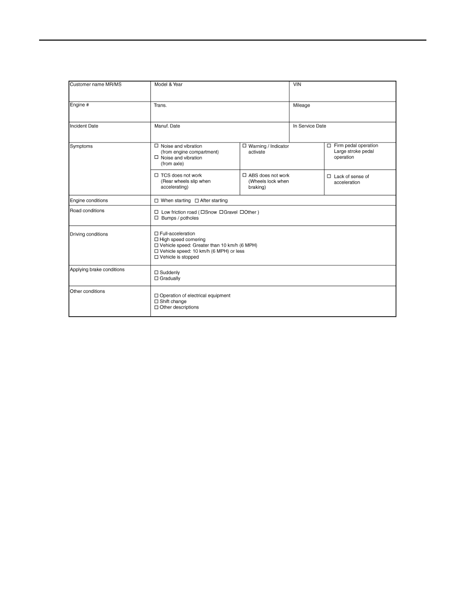
DIAGNOSIS AND REPAIR WORK FLOW

Diagnostic Work Sheet

INFOID:0000000003247125

SFIA3265E

Revision: 2008 October

2009 Murano

INSPECTION AND ADJUSTMENT

BRC-9

< BASIC INSPECTION >

[VDC/TCS/ABS]

C

D

E

G

H

I

J

K

L

M

A

B

BRC

N

O

P

INSPECTION AND ADJUSTMENT

ADJUSTMENT OF STEERING ANGLE SENSOR NEUTRAL POSITION

ADJUSTMENT OF STEERING ANGLE SENSOR NEUTRAL POSITION : Description

INFOID:0000000003247126

When doing work that applies to the list below, make sure to adjust neutral position of steering angle sensor
before running vehicle.

×

: Required –: Not required

ADJUSTMENT OF STEERING ANGLE SENSOR NEUTRAL POSITION : Special Re-
pair Requirement

INFOID:0000000003247127

ADJUSTMENT OF STEERING ANGLE SENSOR NEUTRAL POSITION

CAUTION:

To adjust neutral position of steering angle sensor, make sure to use CONSULT-III
(Adjustment cannot be done without CONSULT-III)

1.

ALIGN THE VEHICLE STATUS

Stop the vehicle with front wheels in straight-ahead position.

>> GO TO 2.

2.

PERFORM THE NEUTRAL POSITION ADJUSTMENT FOR THE STEERING ANGLE SENSOR

1.

On the CONSULT-III screen, touch "WORK SUPPORT" and "ST ANGLE SENSOR ADJUSTMENT" in
order.

2.

Touch “START”.

CAUTION:

Do not touch steering wheel while adjusting steering angle sensor.

3.

After approximately 10 seconds, touch “END”.
NOTE:
After approximately 60 seconds, it ends automatically.

4.

Turn the ignition switch OFF, then turn it ON again.

CAUTION:

Be sure to perform above operation.

>> GO TO 3.

3.

CHECK DATA MONITOR

1.

Run the vehicle with front wheels in straight-ahead position, then stop.

2.

Select “STR ANGLE SIG” in “DATA MONITOR” and check steering angle sensor signal.

Situation

Adjustment of steering angle sensor neutral position

Removing/Installing ABS actuator and electric unit (control unit)

Replacing ABS actuator and electric unit (control unit)

×

Removing/Installing steering angle sensor

×

Replacing steering angle sensor

×

Removing/Installing steering components

×

Replacing steering components

×

Removing/Installing suspension components

×

Replacing suspension components

×

Change tires to new ones

Tire rotation

Adjusting wheel alignment

×

STR ANGLE SIG

: 0

±

2.5

°

Revision: 2008 October

2009 Murano

BRC-10

< BASIC INSPECTION >

[VDC/TCS/ABS]

INSPECTION AND ADJUSTMENT

Is the steering angle within the specified range?

YES

>> GO TO 4.

NO

>> Perform the neutral position adjustment for the steering angle sensor again, GO TO 1.

4.

ERASE THE SELF-DIAGNOSIS MEMORY

Erase the self-diagnosis memories of the ABS actuator and electric unit (control unit) and ECM.
• ABS actuator and electric unit (control unit): Refer to 

BRC-29, "CONSULT-III Function"

.

• ECM: Refer to 

EC-102, "Diagnosis Description"

.

Are the memories erased?

YES

>> INSPECTION END

NO

>> Check the items indicated by the self-diagnosis.

CALIBRATION OF YAW RATE/SIDE/DECEL G SENSOR

CALIBRATION OF YAW RATE/SIDE/DECEL G SENSOR : Description

INFOID:0000000003247292

When doing work that applies to the list below, make sure to calibration of yaw rate/side/decel G sensor before
running vehicle.

×

: Required –: Not required

CALIBRATION OF YAW RATE/SIDE/DECEL G SENSOR : Special Repair Require-
ment

INFOID:0000000003247293

CALIBRATION OF YAW RATE/SIDE/DECEL G SENSOR

CAUTION:

• To calibrate yaw rate/side/decel G sensor, make sure to use CONSULT-III.

(Calibration cannot be done without CONSULT-III.)

• Perform the G sensor calibration only with the vehicle parked on level surface.

1.

ALIGN THE VEHICLE STATUS

Stop the vehicle with front wheels in straight-ahead position.

CAUTION:

• Keep all tires inflated to correct pressures. Adjust the tire pressure to the specified pressure value.
• Check that there is specified-load in vehicle other than the driver (or equivalent weight placed in

driver

s position).

>> GO TO 2.

2.

PERFORM THE CALIBRATION OF YAW RATE/SIDE/DECEL G SENSOR

1.

On the CONSULT-III screen, touch “WORK SUPPORT” and “DECEL G SEN CALIBRATION” in order.

2.

Touch “START”.

3.

After approximately 10 seconds, touch “END”.
NOTE:
After approximately 60 seconds, it ends automatically.

4.

Turn the ignition switch OFF, then turn it ON again.

CAUTION:

Be sure to perform above operation.

Situation

Calibration of yaw rate/side/decel G sensor

Removing/Installing ABS actuator and electric unit (control unit)

×

Replacing ABS actuator and electric unit (control unit)

×

Removing/Installing steering components

Removing/Installing suspension components

Change tires to new ones

Tire rotation

Adjusting wheel alignment

Removing/Installing yaw rate/side/decel G sensor

×

Replacing yaw rate/side/decel G sensor

×

Revision: 2008 October

2009 Murano

INSPECTION AND ADJUSTMENT

BRC-11

< BASIC INSPECTION >

[VDC/TCS/ABS]

C

D

E

G

H

I

J

K

L

M

A

B

BRC

N

O

P

>> GO TO 3.

3.

CHECK DATA MONITOR

1.

Run the vehicle with front wheels in straight-ahead position, then stop.

2.

Select “DECEL G-SEN” in “DATA MONITOR” and check yaw rate/side/decel G sensor signal.

Is the yaw rate/side/decel G within the specified range?

YES

>> GO TO 4.

NO

>> Perform the calibration of yaw rate/side/decel G sensor again, GO TO 1.

4.

ERASE THE SELF-DIAGNOSIS MEMORY

Erase the self-diagnosis memories of the ABS actuator and electric unit (control unit) and ECM.
• ABS actuator and electric unit (control unit): Refer to 

BRC-29, "CONSULT-III Function"

.

• ECM: Refer to 

EC-102, "Diagnosis Description"

.

Are the memories erased?

YES

>> INSPECTION END

NO

>> Check the items indicated by the self-diagnosis.

CALIBRATION OF PRESSURE SENSOR

CALIBRATION OF PRESSURE SENSOR : Description

INFOID:0000000004684882

When doing work that applies to the list below, make sure to calibrate pressure sensor before running vehicle.

×

: Required –: Not required

CALIBRATION OF PRESSURE SENSOR : Special Repair Requirement

INFOID:0000000004684883

CALIBRATION OF PRESSURE SENSOR

CAUTION:

• To calibrate pressure sensor, make sure to use CONSULT-III.

(Calibration cannot be done without CONSULT-III.)

• Perform the pressure sensor calibration with the vehicle stopped.
• Never depress the brake pedal during the pressure sensor calibration.

1.

PERFORM THE CALIBRATION OF PRESSURE SENSOR

1.

On the CONSULT-III screen, touch “WORK SUPPORT” and “PRESS SEN CALIBRATION” in order.

2.

Touch “START”.

3.

After approximately 10 seconds, touch “END”.

4.

Turn the ignition switch OFF, then turn it ON again.

CAUTION:

Always perform the above operation.

>> GO TO 2.

2.

CHECK DATA MONITOR

Select “PRESS SENSOR” in “DATA MONITOR” and check pressure sensor signal.

DECEL G-SEN

±

0.08 G

Situation

Calibration of pressure sensor

Removing/Installing ABS actuator and electric unit (control unit)

Replacing ABS actuator and electric unit (control unit)

×

Removing/Installing brake components

Replacing brake components

Performing air bleeding from brake piping

Replacing brake fluid

Revision: 2008 October

2009 Murano

BRC-12

< BASIC INSPECTION >

[VDC/TCS/ABS]

INSPECTION AND ADJUSTMENT

Is the pressure within the specified range?

YES

>> GO TO 3.

NO

>> Check pressure sensor. Refer to 

BRC-64, "Diagnosis Procedure"

.

3.

ERASE THE SELF-DIAGNOSIS MEMORY

Erase the self-diagnosis memories of the ABS actuator and electric unit (control unit).

Are the memories erased?

YES

>> INSPECTION END

NO

>> Check the items indicated by the self-diagnosis.

Condition

DATA MONITOR

Brake pedal is released

Approx. 0 bar

Brake pedal is depressed

Approx. 

40 – 300 bar

Revision: 2008 October

2009 Murano

VDC

BRC-13

< FUNCTION DIAGNOSIS >

[VDC/TCS/ABS]

C

D

E

G

H

I

J

K

L

M

A

B

BRC

N

O

P

FUNCTION DIAGNOSIS

VDC

System Diagram

INFOID:0000000003247128

System Description

INFOID:0000000003247129

• In addition to the TCS/ABS function, the driver steering amount and brake operation amount are detected by

the steering angle sensor and pressure sensor, and the vehicle

s driving status (amount of under steering/

over steering) is determined by the information from the yaw rate/side/decel G sensor, wheel sensor, etc.,
and this information is used to improve vehicle stability by controlling the braking and engine power to all
four wheels.

• The SLIP indicator lamp flashes to inform the driver of VDC operation.
• During VDC operation, the body and brake pedal lightly vibrate and mechanical noises may be heard. This is

normal.

• The ABS warning lamp, VDC OFF indicator lamp, and SLIP indicator lamp might turn ON when the vehicle

is subject to strong shaking or large vibration, such as when the vehicle is on a turn table or a ship while the
engine is running or steep slope such as bank. In this case, restart the engine on a normal road, and if the
ABS warning lamp, VDC OFF indicator lamp, and SLIP indicator lamp turn OFF, there is no malfunction.

Component Parts Location

INFOID:0000000003247130

FOR USA

JSFIA0210GB

Revision: 2008 October

2009 Murano

BRC-14

< FUNCTION DIAGNOSIS >

[VDC/TCS/ABS]

VDC

1.

Steering angle sensor

2.

ABS warning lamp

3.

Brake warning lamp

4.

VDC OFF indicator lamp

5.

SLIP indicator lamp

6.

ABS actuator and electric unit (con-
trol unit)

7.

Front wheel sensor

8.

Yaw rate/side/decel G sensor

9.

VDC OFF switch

10. Rear wheel sensor

JSFIA0208ZZ

Revision: 2008 October

2009 Murano

VDC

BRC-15

< FUNCTION DIAGNOSIS >

[VDC/TCS/ABS]

C

D

E

G

H

I

J

K

L

M

A

B

BRC

N

O

P

EXCEPT FOR USA

A.

Back of spiral cable assembly

B.

Combination meter

C.

Engine room (right side)

D.

Steering knuckle

E.

Under center console

F.

Instrument driver lower panel

G.

Rear axle

JSFIA0209ZZ

Revision: 2008 October

2009 Murano

BRC-16

< FUNCTION DIAGNOSIS >

[VDC/TCS/ABS]

VDC

Component Description

INFOID:0000000003247131

1.

Steering angle sensor

2.

ABS warning lamp

3.

Brake warning lamp

4.

VDC OFF indicator lamp

5.

SLIP indicator lamp

6.

ABS actuator and electric unit (con-
trol unit)

7.

Front wheel sensor

8.

Yaw rate/side/decel G sensor

9.

VDC OFF switch

10. Rear wheel sensor

A.

Back of spiral cable assembly

B.

Combination meter

C.

Engine room (right side)

D.

Steering knuckle

E.

Under center console

F.

Instrument driver lower panel

G.

Rear axle

Component parts

Reference

ABS actuator and electric unit (control unit)

Pump

BRC-44, "Description"

Motor

Actuator relay (Main relay)

BRC-62, "Description"

Solenoid valve

BRC-54, "Description"

VDC switch-over valve (CV1, CV2)

BRC-73, "Description"

VDC switch-over valve (SV1, SV2)

BRC-75, "Description"

Wheel sensor

BRC-34, "Description"

Yaw rate/side/decel G sensor

BRC-46, "Description"

Steering angle sensor

BRC-66, "Description"

VDC OFF switch

BRC-82, "Description"

ABS warning lamp

BRC-84, "Description"

Brake warning lamp

BRC-85, "Description"

VDC OFF indicator lamp

BRC-86, "Description"

SLIP indicator lamp

BRC-87, "Description"

Revision: 2008 October

2009 Murano

TCS

BRC-17

< FUNCTION DIAGNOSIS >

[VDC/TCS/ABS]

C

D

E

G

H

I

J

K

L

M

A

B

BRC

N

O

P

TCS

System Diagram

INFOID:0000000003305333

System Description

INFOID:0000000003247133

• The wheel spin of the drive wheels is detected by the ABS actuator and electric unit (control unit) using the

wheel speed signals from the four wheels, so if wheel spin occurs, the drive wheel right and left brake fluid
pressure control and engine fuel cut are conducted while the throttle valve opening is restricted to reduce the
engine torque and decrease the amount of wheel spin. In addition, the throttle opening is controlled to
achieve the optimum engine torque.

• Depending on road circumstances, the driver may have a sluggish feel. This is normal, because the opti-

mum traction has the highest priority under TCS operation.

• TCS may be activated any time the vehicle suddenly accelerates, depressing accelerator pedal fully, sud-

denly downshifts, upshifts, or is driven on a road with a varying surface friction coefficient.

• During TCS operation, TCS informs a driver of system operation by flashing SLIP indicator lamp.

Component Parts Location

INFOID:0000000003305334

FOR USA

JSFIA0210GB

Revision: 2008 October

2009 Murano

BRC-18

< FUNCTION DIAGNOSIS >

[VDC/TCS/ABS]

TCS

1.

Steering angle sensor

2.

ABS warning lamp

3.

Brake warning lamp

4.

VDC OFF indicator lamp

5.

SLIP indicator lamp

6.

ABS actuator and electric unit (con-
trol unit)

7.

Front wheel sensor

8.

Yaw rate/side/decel G sensor

9.

VDC OFF switch

10. Rear wheel sensor

JSFIA0208ZZ

Revision: 2008 October

2009 Murano

TCS

BRC-19

< FUNCTION DIAGNOSIS >

[VDC/TCS/ABS]

C

D

E

G

H

I

J

K

L

M

A

B

BRC

N

O

P

EXCEPT FOR USA

A.

Back of spiral cable assembly

B.

Combination meter

C.

Engine room (right side)

D.

Steering knuckle

E.

Under center console

F.

Instrument driver lower panel

G.

Rear axle

JSFIA0209ZZ

Revision: 2008 October

2009 Murano

BRC-20

< FUNCTION DIAGNOSIS >

[VDC/TCS/ABS]

TCS

Component Description

INFOID:0000000003305335

1.

Steering angle sensor

2.

ABS warning lamp

3.

Brake warning lamp

4.

VDC OFF indicator lamp

5.

SLIP indicator lamp

6.

ABS actuator and electric unit (con-
trol unit)

7.

Front wheel sensor

8.

Yaw rate/side/decel G sensor

9.

VDC OFF switch

10. Rear wheel sensor

A.

Back of spiral cable assembly

B.

Combination meter

C.

Engine room (right side)

D.

Steering knuckle

E.

Under center console

F.

Instrument driver lower panel

G.

Rear axle

Component parts

Reference

ABS actuator and electric unit (control unit)

Pump

BRC-44, "Description"

Motor

Actuator relay (Main relay)

BRC-62, "Description"

Solenoid valve

BRC-54, "Description"

VDC switch-over valve (CV1, CV2)

BRC-73, "Description"

VDC switch-over valve (SV1, SV2)

BRC-75, "Description"

Wheel sensor

BRC-34, "Description"

Yaw rate/side/decel G sensor

BRC-46, "Description"

Steering angle sensor

BRC-66, "Description"

VDC OFF switch

BRC-82, "Description"

ABS warning lamp

BRC-84, "Description"

Brake warning lamp

BRC-85, "Description"

VDC OFF indicator lamp

BRC-86, "Description"

SLIP indicator lamp

BRC-87, "Description"

Revision: 2008 October

2009 Murano

ABS

BRC-21

< FUNCTION DIAGNOSIS >

[VDC/TCS/ABS]

C

D

E

G

H

I

J

K

L

M

A

B

BRC

N

O

P

ABS

System Diagram

INFOID:0000000003305336

System Description

INFOID:0000000003247137

• The Anti-Lock Braking System detects wheel revolution while braking, and it improves handling stability dur-

ing sudden braking by electrically preventing 4 wheel lock. Maneuverability is also improved for avoiding
obstacles.

• If the electrical system malfunction, then fail-safe function is activated, ABS becomes inoperative, and ABS

warning lamp turns ON.

• Electrical system diagnosis by CONSULT-III is available.
• During ABS operation, brake pedal lightly vibrates and a mechanical noise may be heard. This is normal.
• Just after starting the vehicle after the ignition switch ON, brake pedal may vibrate or motor operating noise

may be heard from engine component. This is a normal status of operation check.

• Stopping distance may be longer than that of vehicles without ABS when vehicle drives on rough, gravel, or

snow-covered (fresh, deep snow) roads.

Component Parts Location

INFOID:0000000003305337

FOR USA

JSFIA0210GB

Revision: 2008 October

2009 Murano

BRC-22

< FUNCTION DIAGNOSIS >

[VDC/TCS/ABS]

ABS

1.

Steering angle sensor

2.

ABS warning lamp

3.

Brake warning lamp

4.

VDC OFF indicator lamp

5.

SLIP indicator lamp

6.

ABS actuator and electric unit (con-
trol unit)

7.

Front wheel sensor

8.

Yaw rate/side/decel G sensor

9.

VDC OFF switch

10. Rear wheel sensor

JSFIA0208ZZ

Revision: 2008 October

2009 Murano

ABS

BRC-23

< FUNCTION DIAGNOSIS >

[VDC/TCS/ABS]

C

D

E

G

H

I

J

K

L

M

A

B

BRC

N

O

P

EXCEPT FOR USA

A.

Back of spiral cable assembly

B.

Combination meter

C.

Engine room (right side)

D.

Steering knuckle

E.

Under center console

F.

Instrument driver lower panel

G.

Rear axle

JSFIA0209ZZ

Revision: 2008 October

2009 Murano


Content      ..     71      72      73      74     ..