Nissan Murano Z51 (2008 year). Manual - part 8
TELESCOPIC MOTOR
ADP-109
< COMPONENT DIAGNOSIS >
C
D
E
F
G
H
I
K
L
M
A
B
ADP
N
O
P
TELESCOPIC MOTOR
Description
INFOID:0000000003312475
• The telescopic motor is installed to the steering column assembly.
• The telescopic motor is activated with the automatic drive positioner control unit.
• Compresses the steering column by changing the rotation direction of telescopic motor.
Component Function Check
INFOID:0000000003312476
1.
CHECK FUNCTION
1.
Select “TELESCO MOTOR” in “Active test” mode with CONSULT-III.
2.
Check the telescopic motor operation.
Is the operation of relevant parts normal?
YES
>> INSPECTION END
NO
>> Perform diagnosis procedure. Refer to
ADP-109, "Diagnosis Procedure"
Diagnosis Procedure
INFOID:0000000003312477
1.
CHECK TELESCOPIC MOTOR POWER SUPPLY
1.
Turn ignition switch OFF.
2.
Disconnect telescopic motor connector.
3.
Turn the ignition switch ON.
4.
Perform “Active test” (“TELESCO MOTOR”) with CONSULT-lll
5.
Check voltage between telescopic motor harness connector and ground.
Is the inspection result normal?
YES
>> Replace telescopic motor. (Built in steering column assembly.)
NO
>> GO TO 2.
2.
CHECK TELESCOPIC MOTOR CIRCUIT
1.
Turn ignition switch OFF.
2.
Disconnect automatic drive positioner control unit.
3.
Check continuity between automatic drive positioner control unit harness connector and telescopic motor
harness connector.
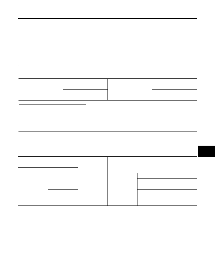
Test item
Description
TELESCO MOTOR
OFF
Steering telescopic
Stop
FR Forward
RR
Backward
(+)
(–)
Condition
Voltage (V)
(Approx.)
Telescopic motor
Connector
Terminals
M117
1
Ground
TELESCOPIC MO-
TOR
OFF
0
FR (forward)
0
RR (backward)
Battery voltage
2
OFF
0
FR (forward)
Battery voltage
RR (backward)
0
Revision: 2008 October
2009 Murano