Nissan Murano. Manual - part 809


  Главная      Nissan     Nissan Murano (2014 year) - Service Manual


поиск по сайту            


содержание   ..  807  808  809  810   ..


Nissan Murano. Manual - part 809


HAC-10

< BASIC INSPECTION >

[WITHOUT 7 INCH DISPLAY]

INSPECTION AND ADJUSTMENT

9.

CHECK LH/RH INDEPENDENT TEMPERATURE ADJUSTMENT FUNCTION

1.

Press the DUAL switch, and then check that “DUAL” is shown on the display. 

2.

Operate the temperature control switch (driver side). Check that the discharge air temperature (driver
side) changes. 

3.

Operate the temperature control switch (passenger side). Check that the discharge air temperature (pas-
senger side) changes. 

4.

Press the DUAL switch, and then check that the temperature setting (LH/RH) is unified to the driver side
temperature setting. 

Is the inspection result normal?

YES

>> GO TO 10.

NO

>> Refer to 

HAC-108, "Diagnosis Chart By Symptom"

 and perform the appropriate diagnosis. 

10.

CHECK AUTO MODE

1.

Press the AUTO switch, and then check that “AUTO” is shown on the display. 

2.

Operate the temperature control switch (driver side). Check that the fan speed or outlet changes (the dis-
charge air temperature or fan speed varies depending on the ambient temperature, in-vehicle tempera-
ture, and temperature setting). 

Is the inspection result normal?

YES

>> INSPECTION END

NO

>> Refer to 

HAC-108, "Diagnosis Chart By Symptom"

 and perform the appropriate diagnosis. 

Temperature Setting Trimmer

INFOID:0000000009722026

Description

If the temperature felt by the customer is different than the air flow temperature controlled by the temperature
setting, the auto amplifier control temperature can be adjusted to compensate for the temperature setting. 

How to set

Using CONSULT, perform “TEMP SET CORRECT” on “WORK SUPPORT” of HVAC. 

NOTE:

• When the temperature setting is set to 25.0

°

C (77

°

F) and 

3.0

°

C (

6

°

F), the temperature controlled by auto amp is 25.0

°

C (77

°

F) 

3.0

°

C (6

°

F) = 22.0

°

C (71

°

F) and the temperature becomes lower than the temperature setting. 

• When the battery cable is disconnected from the negative terminal or when the battery voltage becomes 10V or less, the setting of the

difference between the temperature setting and control temperature may be cancelled. 

Foot Position Setting Trimmer

INFOID:0000000009722027

Description

In the FOOT mode, the air blowing to the DEF can be turned ON/OFF. 
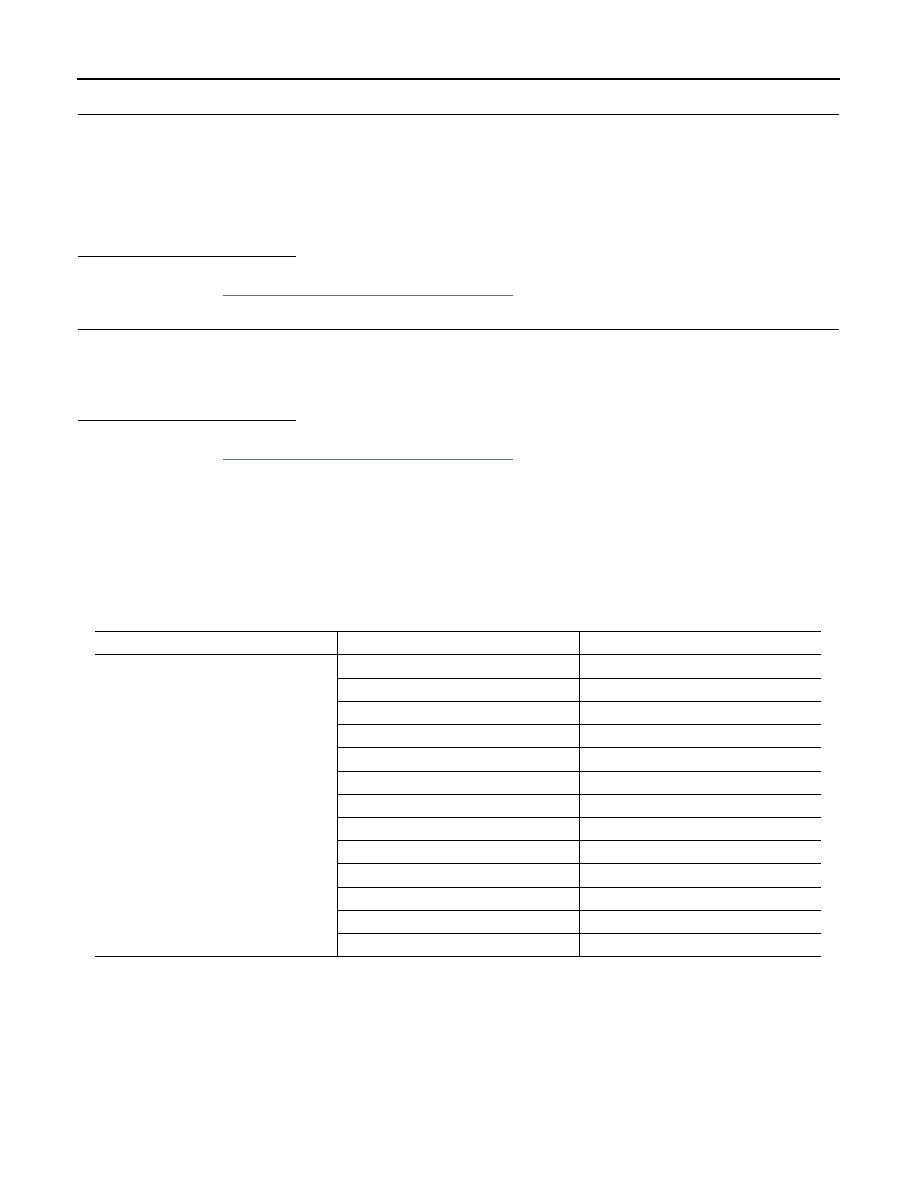
Work support items

Display (

°

F)

Display (

°

C)

TEMP SET CORRECT

6

3.0

5

2.5

4

2.0

3

1.5

2

1.0

1

0.5

0 (initial status)

0 (initial status)

1

0.5

2

1.0

3

1.5

4

2.0

5

2.5

6

3.0

INSPECTION AND ADJUSTMENT

HAC-11

< BASIC INSPECTION >

[WITHOUT 7 INCH DISPLAY]

C

D

E

F

G

H

J

K

L

M

A

B

HAC

N

O

P

How to set

Using CONSULT, perform “BLOW SET” on “WORK SUPPORT” of HVAC. 

NOTE:
When the battery cable is disconnected from the negative terminal or when the battery voltage becomes 10V
or less, the setting of the discharge air mix ratio in FOOT mode may be cancelled. 

Inlet Port Memory Function (FRE)

INFOID:0000000009722028

Description

• If the ignition switch is turned to the OFF position while the FRE switch is set to ON (fresh air intake), “Per-

form the memory” or “Do not perform the memory” of the FRE switch ON (fresh air intake) condition can be
selected. 

• If “Perform the memory” was set, the FRE switch will be ON (fresh air intake) when turning the ignition switch

to the ON position again. 

• If “Do not perform the memory” was set, the air inlets will be controlled automatically when turning the igni-

tion switch to the ON position again. 

How to set

Using CONSULT, perform “FRE MEMORY SET” on “WORK SUPPORT” of HVAC. 

NOTE:

When the battery cable is disconnected from the negative terminal or when the battery voltage becomes 10 V or less, the setting of the
FRE switch memory function may be cancelled. 

Inlet Port Memory Function (REC)

INFOID:0000000009722029

Description

• If the ignition switch is turned to the OFF position while the REC switch is set to ON (recirculation), “Perform

the memory” or “Do not perform the memory” of the REC switch ON (recirculation) condition can be
selected. 

• If “Perform the memory” was set, the REC switch will be ON (recirculation) when turning the ignition switch

to the ON position again. 

• If “Do not perform the memory” was set, the air inlets will be controlled automatically when turning the igni-

tion switch to the ON position again. 

How to set

Using CONSULT, perform “REC MEMORY SET” on “WORK SUPPORT” of HVAC. 

NOTE:

When the battery cable is disconnected from the negative terminal or when the battery voltage becomes 10 or less, the setting of the
REC switch memory function may be cancelled. 

Work support items

Display

DEF door position

Auto control

Manual control

BLOW SET

Mode 1

OPEN

CLOSE

Mode 2 (initial status)

OPEN

OPEN

Mode 3

CLOSE

OPEN

Mode 4

CLOSE

CLOSE

Work support items

Display

Setting

FRE MEMORY SET

WITHOUT

Perform the memory of manual FRE

WITH (initial status)

Do not perform the memory of manual FRE (auto 
control)

Work support items

Display

Setting

REC MEMORY SET

WITHOUT (initial status)

Perform the memory of manual REC

WITH

Do not perform the memory of manual REC (auto 
control)

HAC-12

< SYSTEM DESCRIPTION >

[WITHOUT 7 INCH DISPLAY]

COMPRESSOR CONTROL FUNCTION

SYSTEM DESCRIPTION

COMPRESSOR CONTROL FUNCTION

Description

INFOID:0000000009722030

PRINCIPLE OF OPERATION

Compressor is not activated.

Functional circuit diagram

Functional initial inspection chart

×

: Applicable

CAN (1)

: A/C switch signal
: Blower fan motor switch signal

CAN (2)

: A/C Compressor request signal

RX, TX

: A/C switch signal
: Fan ON signal
: Defroster signal

JPIIA0483GB

Control unit

Diagnosis item

Location

A

B

C

D

A/C auto amp.

 “HVAC”

Self-diagnosis

×

Data monitor

×

Active test

×

×

ECM

 “ENGINE”

Self-diagnosis function
(CAN system diagnosis)

×

Data monitor

×

×

IPDM E/R

 “IPDM E/R”

Self-diagnosis function
(CAN system diagnosis)

×

Data monitor

×

Auto active test

×

COMPRESSOR CONTROL FUNCTION

HAC-13

< SYSTEM DESCRIPTION >

[WITHOUT 7 INCH DISPLAY]

C

D

E

F

G

H

J

K

L

M

A

B

HAC

N

O

P

Component Part Location

INFOID:0000000009722031

ENGINE COMPARTMENT

PASSENGER COMPARTMENT

1.

Refrigerant pressure sensor

2.

Compressor (magnet clutch)

3.

Ambient sensor

JPIIA0607ZZ


содержание   ..  807  808  809  810   ..