Nissan Murano. Manual - part 425


  Главная      Nissan     Nissan Murano (2014 year) - Service Manual


поиск по сайту            


содержание   ..  423  424  425  426   ..


Nissan Murano. Manual - part 425


HOOD

DLK-311

< REMOVAL AND INSTALLATION >

[WITH INTELLIGENT KEY SYSTEM]

C

D

E

F

G

H

I

J

L

M

A

B

DLK

N

O

P

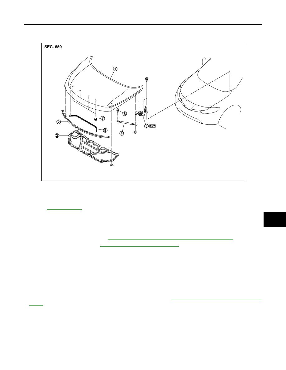
HOOD HINGE : Exploded View

INFOID:0000000009719215

HOOD HINGE : Removal and Installation

INFOID:0000000009719216

REMOVAL

1.

Remove hood assembly. Refer to 

DLK-308, "HOOD ASSEMBLY : Removal and Installation"

.

2.

Remove front fender. Refer to 

DLK-316, "Removal and Installation"

.

3.

Remove hood hinge mounting bolts, and then remove hood hinge.

INSTALLATION

Install in the reverse order of removal.

CAUTION:

• Before installation of hood hinge, apply anticorrosive agent onto the mounting surface of the vehicle

body.

• After installation, apply touch-up paint (the body color) onto the head of the hinge mounting bolts

and nuts.

• After installation, perform hood fitting adjustment. Refer to 

DLK-309, "HOOD ASSEMBLY : Adjust-

ment"

.

HOOD STAY

1.

Hood assembly

2.

Hood front seal

3.

Hood insulator

4.

Hood stay

5.

Hood hinge

6.

Stud ball

7.

Hood bumper rubber

8.

Radiator core seal

Refer to 

GI-4, "Components"

 for symbols in the figure.

JMKIA1797ZZ

DLK-312

< REMOVAL AND INSTALLATION >

[WITH INTELLIGENT KEY SYSTEM]

HOOD

HOOD STAY : Exploded View

INFOID:0000000009719217

HOOD STAY : Removal and Installation

INFOID:0000000009719218

REMOVAL

1.

Remove the metal clip (3) located on the connection between
the hood stay (1) and the stud ball (2) (hood side), by using a
flat-bladed screwdriver (A).

2.

Disengage the stud ball from the hood stay (hood side).

3.

Repeat the same operation to disengage the stud ball from the
hood stay (body side), then remove the hood stay.

INSTALLATION

Install in the reverse order of removal.

1.

Hood assembly

2.

Hood front seal

3.

Hood insulator

4.

Hood stay

5.

Hood hinge

6.

Stud ball

7.

Hood bumper rubber

8.

Radiator core seal

Refer to 

GI-4, "Components"

 for symbols in the figure.

JMKIA1797ZZ

JMKIA2255ZZ

HOOD

DLK-313

< REMOVAL AND INSTALLATION >

[WITH INTELLIGENT KEY SYSTEM]

C

D

E

F

G

H

I

J

L

M

A

B

DLK

N

O

P

HOOD STAY : Disposal 

INFOID:0000000009719219

1.

Fix hood stay (1) using a vise (C).

2.

Using hacksaw (A) slowly make 2 holes in the hood stay, in
numerical order as shown in the figure.

CAUTION:

• When cutting a hole on hood stay, always cover a hack-

saw using a shop cloth (B) to avoid scattering metal frag-
ments or oil. 

• Wear eye protection (safety glasses).
• Wear gloves.

JMKIA3336ZZ

A:

20 mm (0.787 in)

B:

Cut at the groove.

JMKIA3609ZZ

DLK-314

< REMOVAL AND INSTALLATION >

[WITH INTELLIGENT KEY SYSTEM]

RADIATOR CORE SUPPORT

RADIATOR CORE SUPPORT

Exploded View

INFOID:0000000009719220

Removal and Installation

INFOID:0000000009719221

REMOVAL

1.

Use a refrigerant collecting equipment to discharge the refrigerant. Refer to 

HA-25, "Maintenance of

Lubricant Quantity"

.

2.

Remove front under cover. Refer to 

EXT-29, "Removal and Installation"

.

3.

Drain engine coolant from radiator. Refer to 

CO-11, "Draining"

.

4.

Remove front grille. Refer to 

EXT-21, "Removal and Installation"

.

5.

Remove front bumper fascia, energy absorber, bumper reinforcement. Refer to 

EXT-15, "Removal and

Installation"

.

6.

Remove air duct assembly. Refer to 

EM-31, "Exploded View"

.

7.

Remove hood lock. Refer to 

DLK-338, "Removal and Installation"

.

8.

Remove front combination lamp (RH/LH). Refer to 

EXL-179, "Removal and Installation"

 (XENON TYPE)

or 

EXL-360, "Removal and Installation"

 (HALOGEN TYPE).

9.

Disconnect connector of refrigerant pressure sensor. Refer to 

HA-52, "Exploded View"

.

10. Remove bumper retainer assembly. Refer to 

EXT-15, "Removal and Installation"

.

11. Remove clips, and then remove air guide center and air guide upper.
12. Disengage harness clip from air guide side (RH).

13. Disengage pawls, and then remove air guide side (RH/LH).

14. Remove condenser. Refer to 

HA-50, "Removal and Installation"

.

1.

Air guide upper

2.

Air guide side (RH/LH)

3.

Radiator core support

4.

Air guide center

: Pawl

JMKIA1805ZZ


содержание   ..  423  424  425  426   ..