содержание .. 318 319 320 321 ..
Nissan Murano. Manual - part 320
DAS-170
< DTC/CIRCUIT DIAGNOSIS >
[BSW]
WARNING SYSTEMS ON INDICATOR CIRCUIT
4.
CHECK WARNING SYSTEMS ON INDICATOR
Check the warning systems ON indicator. Refer to
DAS-170, "Component Inspection"
Is the inspection result normal?
YES
>> Replace the camera control unit. Refer to
DAS-187, "Removal and Installation"
.
NO
>> Replace warning systems switch.
DAS-194, "Removal and Installation"
.
Component Inspection
INFOID:0000000009723377
1.
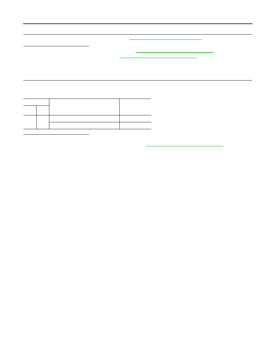
CHECK WARNING SYSTEMS ON INDICATOR
Apply battery voltage to warning systems switch terminals 1 and 2, and then check if the warning systems ON
indicator illuminates.
Is the inspection result normal?
YES
>> INSPECTION END
NO
>> Replace the warning systems switch. Refer to
DAS-194, "Removal and Installation"
Terminals
Condition
Warning sys-
tems ON indica-
tor
(+)
(-)
3
2
When the battery voltage is applied
On
When the battery voltage is not applied
Off