содержание .. 207 208 209 210 ..
Nissan Murano. Manual - part 209
BR-46
< REMOVAL AND INSTALLATION >
FRONT DISC BRAKE
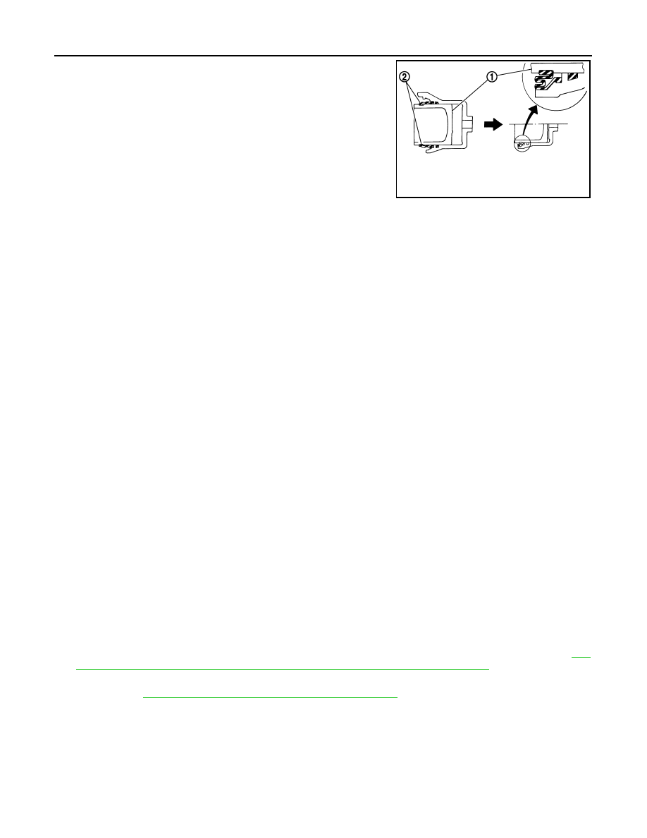
4.
Apply brake fluid to pistons (1). Push piston into cylinder body
by hand and push piston boot (2) piston-side lip into the piston
groove.
CAUTION:
Press the piston evenly and vary the pressing point to pre-
vent cylinder inner wall from being rubbed.
5.
Apply rubber grease to bushing, install bushing to sliding pin.
6.
Apply rubber grease to sliding pins and sliding pin boots, install
sliding pins and sliding pin boots to torque member.
7.
Install the cylinder body to the torque member and tighten the
sliding pin bolts to the specified torque.
BRAKE CALIPER ASSEMBLY (2 PISTON TYPE) : Inspection
INFOID:0000000009722347
INSPECTION AFTER DISASSEMBLY
Cylinder Body
Check the inner wall of the cylinder for rust, wear, cracks or damage. Replace the cylinder if any abnormal
condition is detected.
CAUTION:
Always clean with new brake fluid. Never clean with mineral oil such as gasoline and light oil.
Torque Member
Check the torque member for rust, wear, cracks or damage. Replace the member if any abnormal condition is
detected.
Pistons
Check the surface of the piston for rust, wear, cracks or damage. Replace the piston if any abnormal condition
is detected.
CAUTION:
A piston sliding surface is plated. Never polish with sandpaper.
Sliding Pin and Sliding Pin Boot
Check the sliding pins and sliding boots for rust, wear, cracks or damage. Replace the parts if any abnormal
condition is detected.
INSPECTION AFTER INSTALLATION
1.
Check a drag of front disc brake. If any drag is found, follow the procedure described below.
2.
Remove brake pads.
3.
Press the piston.
CAUTION:
• Never damage the piston boot.
• When replacing a pad with new one, check a brake fluid level in the reservoir tank because brake
fluid returns to master cylinder reservoir tank when pressing piston in.
NOTE:
Use a disc brake piston tool to easily press piston.
4.
Install brake pads.
5.
Depress the brake pedal several times.
6.
Check a drag of front disc brake again. If any drag is found, disassemble the cylinder body. Refer to
44, "BRAKE CALIPER ASSEMBLY (2 PISTON TYPE) : Disassembly and Assembly"
.
7.
Burnish contact surfaces after refinishing or replacing disc rotors, or if a soft pedal occurs at very low mile-
age. Refer to
BR-16, "DISC ROTOR : Inspection and Adjustment"
JPFIA0034ZZ