содержание .. 116 117 118 119 ..
Nissan Murano. Manual - part 118
AV-250
< DTC/CIRCUIT DIAGNOSIS >
[BOSE AUDIO WITHOUT NAVIGATION]
RGB (B: BLUE) SIGNAL CIRCUIT
RGB (B: BLUE) SIGNAL CIRCUIT
Description
INFOID:0000000009721760
Transmit the image displayed with AV control unit with RGB image signal to the display unit.
Diagnosis Procedure
INFOID:0000000009721761
1.
CHECK CONTINUITY RGB (B: BLUE) SIGNAL CIRCUIT
1.
Turn ignition switch OFF.
2.
Disconnect AV control unit connector and display unit connector.
3.
Check continuity between AV control unit harness connector and display unit harness connector.
4.
Check continuity between display unit harness connector and ground.
Is inspection result normal?
YES
>> GO TO 2.
NO
>> Repair harness or connector.
2.
CHECK RGB (B: BLUE) SIGNAL
1.
Connect AV control unit connector and display unit connector.
2.
Turn ignition switch ON.
3.
Check signal between display unit harness connector and ground.
Is inspection result normal?
YES
>> Replace display unit. Refer to
.
NO
>> Replace AV control unit. Refer to
AV control unit
Display unit
Continuity
Connector
Terminal
Connector
Terminal
M172
45
M194
18
Existed
Display unit
Ground
Continuity
Connector
Terminal
M194
18
Not existed
(+)
(
−
)
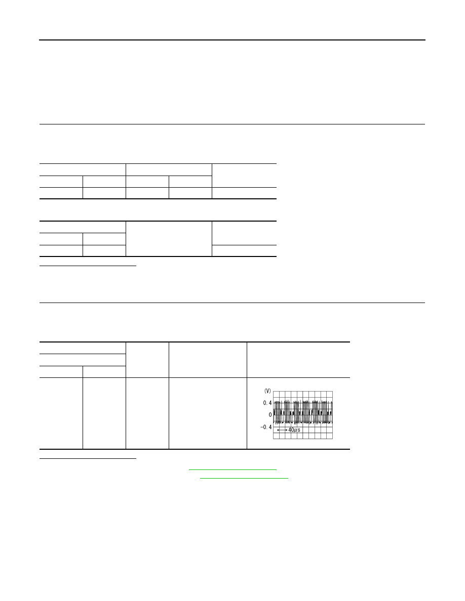
Condition
Reference value
Display unit
Connector
Terminal
M194
18
Ground
Start confirmation/adjust-
ment mode, and then dis-
play color bar by
selecting “Color Spec-
trum Bar” on DISPLAY
DIAGNOSIS screen.
SKIB2237J