содержание .. 1495 1496 1497 1498 ..
Nissan X-Trail 32. Manual - part 1497
LAN-28
< SYSTEM DESCRIPTION >
[CAN]
SYSTEM
SYSTEM
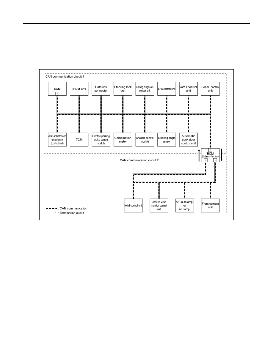
CAN COMMUNICATION SYSTEM
CAN COMMUNICATION SYSTEM : System Description
INFOID:0000000010715305
SYSTEM DIAGRAM
Without forward emergency braking
JSMIA1845GB