Nissan X-Trail 32. Manual - part 1421


  Главная      Nissan     Nissan X-Trail 32 - Service Manual


поиск по сайту            


содержание   ..  1419  1420  1421  1422   ..


Nissan X-Trail 32. Manual - part 1421


SYSTEM

HAC-159

< SYSTEM DESCRIPTION >

[MANUAL AIR CONDITIONING]

C

D

E

F

G

H

J

K

L

M

A

B

HAC

N

O

P

PTC HEATER CONTROL SYSTEM : System Description

INFOID:0000000010939821

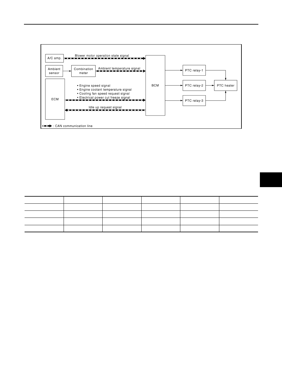
SYSTEM DIAGRAM

DESCRIPTION

• BCM performs PTC relay ON/OFF control based on engine speed, engine coolant temperature, electrical

power cut freeze signal (permission signal, retention signal, stop signal), blower motor operation state sig-
nal, front window defogger state signal, ambient temperature signal, battery voltage, and electrical load state
(high beam request, low beam request, and others).

• When PTC relay turns ON, power supply is supplied to PTC heater. Heating element is heated and air flow

temperature is increased. Heating is available for a period of time until engine coolant temperature is
increased when engine starts cold in cold climate.

• Idle up request signal is transmitted from BCM to ECM while PTC heater operates. Idle speed is increased,

warming-up is facilitated, and battery electric power is obtained.

• Electric power supplied to PTC heating element is subject to PTC relay control conditions. 

NOTE:
PTC heater operation depends on ambient temperature and battery voltage. PTC heater is ON when ambient
temperature is 8

°

C or less. PTC heater is OFF when ambient temperature is 12

°

C (53.6

°

F) or more. PTC

heater is ON when battery voltage is 11.5 V or more. PTC heater is OFF when battery voltage is 11 V or less.

JMIIA3583GB

PTC heater

Operation

PTC relay-1

PTC relay-2

PTC relay-3

Electric power (W)

OFF

OFF

OFF

OFF

OFF

Approx. 0

PTC heater-1

LOW

ON

OFF

OFF

Approx. 333

PTC heater-2

MID

ON

ON

OFF

Approx. 666

PTC heater-3

HI

ON

ON

ON

Approx. 999

HAC-160

< SYSTEM DESCRIPTION >

[MANUAL AIR CONDITIONING]

SYSTEM

PTC HEATER CONTROL SYSTEM : Circuit Diagram

INFOID:0000000010941039

JMIIA3675GB

OPERATION

HAC-161

< SYSTEM DESCRIPTION >

[MANUAL AIR CONDITIONING]

C

D

E

F

G

H

J

K

L

M

A

B

HAC

N

O

P

OPERATION

Switch Name and Function

INFOID:0000000010939822

OPERATION AND DISPLAY OF AUTOMATIC AIR CONDITIONING SYSTEM

Operation: A/C control

INTAKE switch

A/C switch

MAX DEF switch

Fan control dial

MODE DEF switch

MODE VENT switch

MODE FOOT switch

Temperature control dial

Switch name

Function

INTAKE switch

Air inlet changes between recirculation (REC) 

⇔

 fresh air intake (FRE) each time this switch is pressed.

• Switch indicator lamp ON: Recirculation
• Switch indicator lamp OFF: Fresh air intake

A/C switch

Compressor control (switch indicator) changes between ON 

⇔

 OFF each time this switch is pressed 

while blower motor is operated.
NOTE:
A/C switch cannot be turned ON when blower motor is OFF.

MAX DEF switch

MAX DEF mode (switch indicator) changes between ON 

⇔

 OFF each time switch is pressed.

• Air conditioning becomes the following status when MAX DEF mode is turned ON.
- Air outlet: DEF
- Air flow: ON
- Air inlet: Fresh air intake
- A/C switch: ON
• Air conditioning becomes the following status when MAX DEF mode is turned OFF.
- Air outlet: Settings set before DEF mode is turned ON
- Air flow: Settings set before DEF mode is turned ON
- Air inlet: Settings set before DEF mode is turned ON
- A/C switch: Settings set before DEF mode is turned ON

Fan control dial

The air flow can be manually set within the range of speeds 1st - 24th by operating the dial.

JMIIA3578ZZ

HAC-162

< SYSTEM DESCRIPTION >

[MANUAL AIR CONDITIONING]

OPERATION

MODE DEF switch

• Air outlet changes to DEF when this switch is pressed while air conditioning is ON and air outlet con-

dition is automatic control.

• Air outlet changes as following when this switch is pressed while air conditioning is ON and air outlet 

condition is manual control.

- V/D 

⇒

 VENT

- VENT 

⇒

 V/D

- B/L 

⇒

 ALL

- ALL 

⇒

 B/L

- FOOT 

⇒

 D/F

- D/F 

⇒

 FOOT

- DEF 

⇒

 DEF

• When this switch is pressed while air conditioning is ON and MODE DEF is ON, air outlet control is 

changed to automatic control.

• When this switch is pressed while air conditioning is OFF, air conditioning becomes the following status
- Air outlet: DEF
- Air flow: Minimum setting
- Air inlet: Settings set before air conditioning is turned OFF
- A/C switch: Settings set before air conditioning is turned OFF
• When this switch is pressed while MAX DEF is ON, air conditioning becomes the following status
- Air outlet: DEF
- Air flow: Settings set before MAX DEF is turned ON*
- Air inlet: Settings set before MAX DEF is turned ON*
- A/C switch: Settings set before MAX DEF is turned ON*
NOTE:
*: When MAX DEF is turned ON from air conditioning OFF status, each settings set before air condition-
ing is turned OFF.

MODE VENT switch

• Air outlet changes to VENT when this switch is pressed while air conditioning is ON and air outlet con-

dition is automatic control.

• Air outlet changes as following when this switch is pressed while air conditioning is ON and air outlet 

condition is manual control.

- V/D 

⇒

 DEF

- VENT 

⇒

 VENT

- B/L 

⇒

 FOOT

- ALL 

⇒

 D/F

- FOOT 

⇒

 B/L

- D/F 

⇒

 ALL

- DEF 

⇒

 V/D

• When this switch is pressed while air conditioning is ON and MODE VENT is ON, air outlet control is 

changed to automatic control.

• When this switch is pressed while air conditioning is OFF, air conditioning becomes the following status
- Air outlet: VENT
- Air flow: Minimum setting
- Air inlet: Settings set before air conditioning is turned OFF
- A/C switch: Settings set before air conditioning is turned OFF
• When this switch is pressed while MAX DEF is ON, air conditioning becomes the following status
- Air outlet: VENT
- Air flow: Settings set before MAX DEF is turned ON*
- Air inlet: Settings set before MAX DEF is turned ON*
- A/C switch: Settings set before MAX DEF is turned ON*
NOTE:
*: When MAX DEF is turned ON from air conditioning OFF status, each settings set before air condition-
ing is turned OFF.

Switch name

Function


содержание   ..  1419  1420  1421  1422   ..