Nissan X-Trail 32. Manual - part 104


  Главная      Nissan     Nissan X-Trail 32 - Service Manual


поиск по сайту            


содержание   ..  102  103  104  105   ..


Nissan X-Trail 32. Manual - part 104


BR-10

< SYMPTOM DIAGNOSIS >

[LHD]

NOISE, VIBRATION AND HARSHNESS (NVH) TROUBLESHOOTING

SYMPTOM DIAGNOSIS

NOISE, VIBRATION AND HARSHNESS (NVH) TROUBLESHOOTING

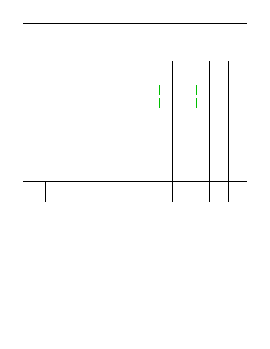
NVH Troubleshooting Chart

INFOID:0000000010838495

Use the chart below to find the cause of the symptom. If necessary, repair or replace these parts.

×

: Applicable

Reference page

BR-17

BR-19

BR-17

BR-19

BR-46

,

BR

-4

9

,

BR-62

BR-17

BR-19

BR-17

BR-19

BR-17

BR-19

BR-17

BR-19

BR-17

BR-19

BR-17

BR-19

BR-17

BR-19

NV

in

 F

A

X

, R

A

X

 a

n

d

 FS

U,

 R

S

U

 s

e

c

tio

n

NV

in

 WT s

e

cti

o

n

NV

in

 WT s

e

cti

o

n

NV

in

 F

A

X

 se

ct

ion

NV

in

 S

T

 s

e

c

ti

o

n

Possible cause and
SUSPECTED PARTS

Pad

s

 da

ma

ge

d

Pad

s

 un

ev

en

 wea

r

Sh

im

s da

ma

ge

d

Roto

r im

b

a

la

nc

e

Ro

to

r da

ma

ge

Rotor runout

Roto

r d

e

fo

rma

tio

n

Roto

r d

e

fl

ectio

n

Rotor rust

Roto

r th

ickn

ess 

va

ria

tio

n

AXLE AND SUSPE

NSION

TIRE

ROA

D

 WHEEL

D

R

IV

E

 SH

AF

T

STEERI

N

G

Symptom

BRAKE

Noise

×

×

×

×

×

×

×

×

×

Shake

×

×

×

×

×

×

Shimmy, Judder

×

×

×

×

×

×

×

×

×

×

×

BRAKE PEDAL

BR-11

< PERIODIC MAINTENANCE >

[LHD]

C

D

E

G

H

I

J

K

L

M

A

B

BR

N

O

P

PERIODIC MAINTENANCE

BRAKE PEDAL

Inspection and Adjustment

INFOID:0000000010838496

INSPECTION

Brake Pedal Height

Check the height (H

1

) between the dash lower panel 

 and the

brake pedal upper surface.

CAUTION:

Remove the floor carpet.

Stop Lamp Switch and Brake Pedal Position Switch (with ASCD).

Check the clearance (C) among the brake pedal bracket 

 and the

stop lamp switch and brake pedal position switch (with ASCD) 
threaded end.

CAUTION:

The stop lamp must turn off when the brake pedal is released.
NOTE:
Pull the brake pedal pad to make the clearance between the stop
lamp switch and brake pedal position switch (with ASCD) threaded
end and the brake pedal lever.

Brake Pedal Play

Press the brake pedal. Check the brake pedal play (A) (stroke until
fluid pressure occurs).

Depressed Brake Pedal Height

Check the height between the dash lower panel 

 and the brake

pedal upper surface (H

2

) when depressing the brake pedal at 490 N

(50 kg, 110 lb) while turning engine ON.

CAUTION:

Remove the floor carpet.

ADJUSTMENT

H

1

: Refer to 

BR-67, "Brake Pedal"

.

JPFIA0065ZZ

C

: Refer to 

BR-67, "Brake Pedal"

.

JPFIA0674ZZ

A

:  Refer  to 

BR-67, "Brake Pedal"

.

JPFIA0277ZZ

H

2

: Refer to 

BR-67, "Brake Pedal"

.

JPFIA0068ZZ

BR-12

< PERIODIC MAINTENANCE >

[LHD]

BRAKE PEDAL

Brake Pedal Height

Perform the following procedure when brake pedal height is not within the specified value because brake
pedal height is not adjustable.
1.

Check input rod length. Refer to 

BR-38, "Inspection and Adjustment"

.

2.

Replace brake pedal assembly when input rod length is within specified value.

Stop Lamp Switch and Brake Pedal Position Switch (with ASCD).

1.

Remove instrument lower panel. Refer to 

IP-14, "Removal and Installation"

.

2.

Disconnect the harness connector from stop lamp switch and brake pedal position switch (with ASCD).

3.

Loosen the stop lamp switch and brake pedal position switch (with ASCD) 45

°

 counterclockwise.

4.

Press-fit the stop lamp switch and brake position switch (with
ASCD) 

 until the stop lamp switch and brake pedal position

switch (with ASCD) hits the brake pedal bracket 

 45

°

 clock-

wise while pulling the brake pedal pad slightly.

CAUTION:

• The clearance (C) between the brake pedal bracket and

stop lamp switch and brake pedal position switch (with
ASCD) threaded end must be the specified value.

• The stop lamp must be turned off when the brake pedal is

released.

Depressed Brake Pedal Height

1.

Perform the air bleeding. Refer to 

BR-14, "Bleeding Brake System"

.

2.

Check the height between the dash lower panel 

 and the

brake pedal upper surface (H

2

) when depressing the brake

pedal at 490 N (50 kg, 110 lb) while turning engine ON.

CAUTION:

Remove the floor carpet.

C

: Refer to 

BR-67, "Brake Pedal"

.

JPFIA0674ZZ

H

2

: Refer to 

BR-67, "Brake Pedal"

.

JPFIA0068ZZ

BRAKE FLUID

BR-13

< PERIODIC MAINTENANCE >

[LHD]

C

D

E

G

H

I

J

K

L

M

A

B

BR

N

O

P

BRAKE FLUID

Inspection

INFOID:0000000010838497

BRAKE FLUID LEVEL

• Check that the brake fluid level in the reservoir tank is within the

standard (between MAX 

 MIN lines).

• Visually check for any brake fluid leakage around the reservoir

tank.

• Check the brake system for any leakage if the fluid level is

extremely low (lower than MIN).

• Check the brake system for fluid leakage if the warning lamp

remains illuminated even after the parking brake is released.

• Check the reservoir tank for the mixing of foreign matter (e.g. dust)

and oils other than brake fluid.

BRAKE LINE

1.

Check brake line (tubes and hoses) for cracks, deterioration or other damage. Replace any damaged
parts.

2.

Depress the brake pedal with a force of 785 N (80 kg, 176 lb)
and hold down the pedal for approximately 5 seconds with the
engine running. Check for any fluid leakage.

CAUTION:

Retighten the applicable connection to the specified torque
and repair any abnormal (damaged, worn or deformed) part
if any brake fluid leakage is present.

Draining

INFOID:0000000010838498

CAUTION:

• Never spill or splash brake fluid on painted surfaces. Brake fluid may seriously damage paint. Wipe it

off immediately and wash with water if it gets on a painted surface. For brake component parts,
never wash them with water.

• Turn the ignition switch OFF and disconnect the ABS actuator and electric unit (control unit) har-

ness connector or the battery negative terminal before performing work.

1.

Connect a vinyl tube to the bleed valve.

2.

Depress the brake pedal and loosen the bleeder valve to gradu-
ally discharge brake fluid.

Refilling

INFOID:0000000010838499

CAUTION:

• Turn the ignition switch OFF and disconnect the ABS actuator and electric unit (control unit) har-

ness connector or the battery negative terminal before performing work.

JPFIA0007ZZ

SBR389C

BRA0007D


содержание   ..  102  103  104  105   ..