Nissan Primera P12. Manual - part 247


  Главная      Nissan     Nissan Primera P12 - Service Manual


поиск по сайту            


содержание   ..  245  246  247  248   ..


Nissan Primera P12. Manual - part 247


DTC P0234 TC SYSTEM

EC-173

[YD (WITH EURO-OBD)]

C

D

E

F

G

H

I

J

K

L

M

A

EC

Diagnostic Procedure

EBS013NF

1.

CHECK VACUUM SOURCE

1.

Turn ignition switch OFF.

2.

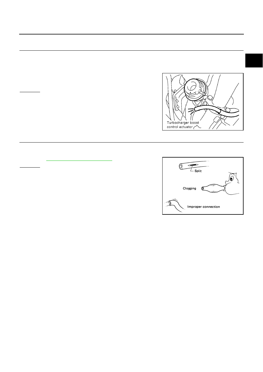
Disconnect vacuum hose connected to turbocharger control actuator.

3.

Start engine and let it idle.

4.

Check vacuum hose for vacuum existence.

OK or NG

OK

>> GO TO 7.

NG

>> GO TO 2.

2.

CHECK VACUUM HOSES AND VACUUM GALLERY

1.

Turn ignition switch OFF.

2.

Check vacuum hoses and vacuum gallery for clogging, cracks or improper connection.
Refer to

EC-22, "Vacuum Hose Drawing"

.

OK or NG

OK

>> GO TO 3.

NG

>> Repair or replace vacuum hoses and vacuum gallery.

Vacuum should exist.

MBIB1023E

SEF109L

EC-174

[YD (WITH EURO-OBD)]

DTC P0234 TC SYSTEM

3.

CHECK TURBOCHARGER BOOST CONTROL SOLENOID VALVE POWER SUPPLY CIRCUIT

1.

Disconnect turbocharger boost control solenoid valve harness
connector.

2.

Turn ignition switch ON.

3.

Check voltage between turbocharger boost control solenoid
valve terminal 2 and ground with CONSULT-II or tester.

OK or NG

OK

>> GO TO 4.

NG

>> Repair open circuit or short to ground or short to power

in harness or connectors.

4.

CHECK TURBOCHARGER BOOST CONTROL SOLENOID VALVE OUTPUT SIGNAL CIRCUIT FOR

OPEN AND SHORT

1.

Turn ignition switch OFF.

2.

Disconnect ECM harness connector.

3.

Check harness continuity between ECM terminal 6 and turbocharger boost control solenoid valve terminal
1.
Refer to Wiring Diagram.

4.

Also check harness for short to ground and short to power.

OK or NG

OK

>> GO TO 5.

NG

>> Repair open circuit or short to ground or short to power in harness or connectors.

5.

CHECK TURBOCHARGE BOOST CONTROL SOLENOID VALVE

Refer to

EC-176, "Component Inspection"

.

OK or NG

OK

>> GO TO 6.

NG

>> Replace turbocharger boost control solenoid valve.

6.

CHECK VACUUM PUMP

Refer to

EM-35, "VACUUM PUMP"

.

OK or NG

OK

>> GO TO 7.

NG

>> Replace vacuum pump assembly.

MBIB0921E

Voltage: Battery voltage

MBIB1101E

Continuity should exist.

DTC P0234 TC SYSTEM

EC-175

[YD (WITH EURO-OBD)]

C

D

E

F

G

H

I

J

K

L

M

A

EC

7.

CHECK TURBOCHARGER BOOST CONTROL ACTUATOR

1.

Turn ignition switch OFF.

2.

Install a vacuum pump to turbocharger boost control actuator.

3.

Make sure that the turbocharger boost control actuator rod
moves smoothly when applying vacuum of -53.3kPa (-533mbar,
-400mmHg, -15.75inHg) and releasing it.

OK or NG

OK

>> GO TO 8.

NG

>> Replace turbocharger assembly.

8.

CHECK TURBOCHARGER BOOST SENSOR

Refer to

EC-181, "Component Inspection"

.

OK or NG

OK

>> GO TO 9.

NG

>> Replace turbocharger boost sensor.

9.

CHECK INTERMITTENT INCIDENT

Refer to

EC-75, "TROUBLE DIAGNOSIS FOR INTERMITTENT INCIDENT"

.

>> INSPECTION END

MBIB1022E

EC-176

[YD (WITH EURO-OBD)]

DTC P0234 TC SYSTEM

Component Inspection

EBS013NG

TURBOCHARGER BOOST CONTROL SOLENOID VALVE

1.

Disconnect turbocharger boost control solenoid valve harness
connector.

2.

Apply 12V direct current between turbocharger boost control solenoid valve terminals.

3.

Check air passage continuity of turbocharger boost control sole-
noid valve under the following conditions.

Operation takes less than 1 second.

If NG, replace turbocharger boost control solenoid valve.

MBIB0921E

CONDITIONS

Air passage continuity

between and B

Air passage continuity

between and C

12V direct current supply
between terminals and 2

Yes

No

No supply

No

Yes

MBIB0996E


содержание   ..  245  246  247  248   ..