Nissan Primera P12. Manual - part 224


  Главная      Nissan     Nissan Primera P12 - Service Manual


поиск по сайту            


содержание   ..  222  223  224  225   ..


Nissan Primera P12. Manual - part 224


MAIN POWER SUPPLY AND GROUND CIRCUIT

EC-81

[YD (WITH EURO-OBD)]

C

D

E

F

G

H

I

J

K

L

M

A

EC

13.

DETECT MALFUNCTIONING PART

Check the following.

20A fuse

Harness connectors E62, F12

Harness for open or short between ECM and fuse

>> Repair open circuit or short to ground or short to power in harness or connectors.

14.

CHECK GROUND CONNECTIONS

1.

Turn ignition switch OFF.

2.

Loosen and retighten ground screws on the body. Refer to

EC-

82, "Ground Inspection"

.

OK or NG

OK

>> GO TO 15.

NG

>> Repair or replace ground connections.

15.

CHECK ECM GROUND CIRCUIT FOR OPEN AND SHORT

1.

Check harness continuity between ECM terminals 1, 2, 3, 114 and body ground. Refer to Wiring Diagram.

2.

Also check harness for short to power.

OK or NG

OK

>> GO TO 16.

NG

>> Repair open circuit or short to power in harness or connectors.

16.

CHECK INTERMITTENT INCIDENT

Refer to

EC-75, "TROUBLE DIAGNOSIS FOR INTERMITTENT INCIDENT"

.

>> INSPECTION END

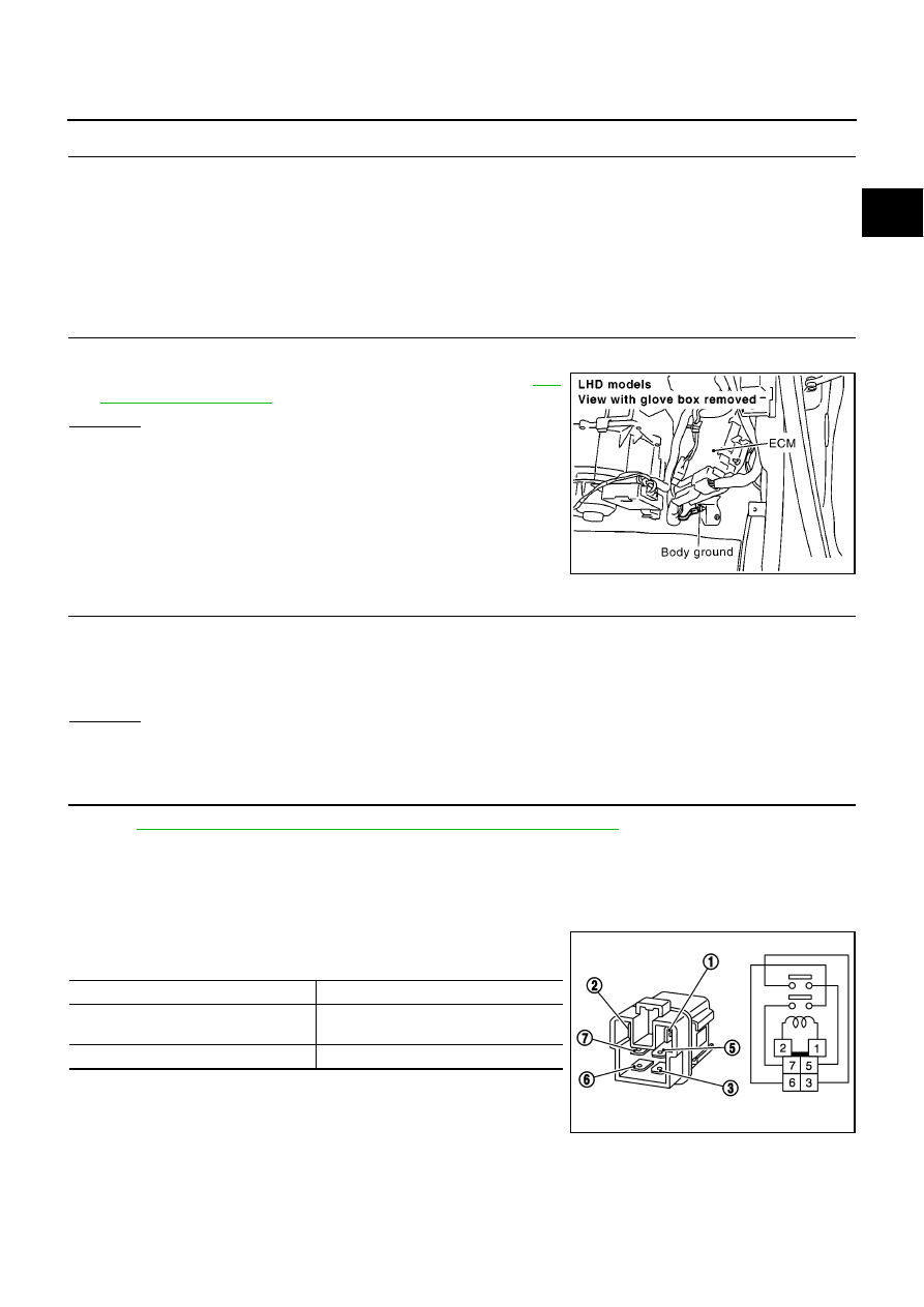
Component Inspection

EBS013K0

ECM RELAY

1.

Apply 12V direct current between ECM relay terminals 1 and 2.

2.

Check continuity between relay terminals 3 and 5, 6 and 7.

3.

If NG, replace ECM relay.

MBIB0915E

Continuity should exist.

Condition

Continuity

12V direct current supply between ter-
minals 1 and 2

Yes

OFF

No

PBIB0077E

EC-82

[YD (WITH EURO-OBD)]

MAIN POWER SUPPLY AND GROUND CIRCUIT

Ground Inspection

EBS013K1

Ground connections are very important to the proper operation of electrical and electronic circuits. Ground
connections are often exposed to moisture, dirt and other corrosive elements. The corrosion (rust) can
become an unwanted resistance. This unwanted resistance can change the way a circuit works.
Electronically controlled circuits are very sensitive to proper grounding. A loose or corroded ground can drasti-
cally affect an electronically controlled circuit. A poor or corroded ground can easily affect the circuit. Even
when the ground connection looks clean, there can be a thin film of rust on the surface.
When inspecting a ground connection follow these rules:

Remove the ground bolt or screw.

Inspect all mating surfaces for tarnish, dirt, rust, etc.

Clean as required to assure good contact.

Reinstall bolt or screw securely.

Inspect for “add-on” accessories which may be interfering with the ground circuit.

If several wires are crimped into one ground eyelet terminal, check for proper crimps. Make sure all of the
wires are clean, securely fastened and providing a good ground path. If multiple wires are cased in one
eyelet make sure no ground wires have excess wire insulation.

For detailed ground distribution information, refer to “Ground Distribution” in PG section.

PBIB1870E

DTC U1000 CAN COMMUNICATION LINE

EC-83

[YD (WITH EURO-OBD)]

C

D

E

F

G

H

I

J

K

L

M

A

EC

DTC U1000 CAN COMMUNICATION LINE

PFP:23710

Description

EBS013K2

CAN (Controller Area Network) is a serial communication line for real time application. It is an on-vehicle mul-
tiplex communication line with high data communication speed and excellent error detection ability. Many elec-
tronic control units are equipped onto a vehicle, and each control unit shares information and links with other
control units during operation (not independent). In CAN communication, control units are connected with 2
communication lines (CAN H line, CAN L line) allowing a high rate of information transmission with less wiring.
Each control unit transmits/receives data but selectively reads required data only.

On Board Diagnosis Logic

EBS013K3

This self-diagnosis has the one trip detection logic.
The MI will not light up for this self-diagnosis.

DTC Confirmation Procedure

EBS013K4

NOTE:
If DTC Confirmation Procedure has been previously conducted, always turn ignition switch OFF and wait at
least 10 seconds before conducting the next test.

WITH CONSULT-II

1.

Turn ignition switch ON and wait at least 3 seconds.

2.

Select “DATA MONITOR” mode with CONSULT-II.

3.

If DTC is detected, go to

EC-85, "Diagnostic Procedure"

.

DTC No.

Trouble diagnosis

name

DTC detecting condition

Possible cause

U1000

CAN communication
line

ECM can not communicate to other control
unit.

ECM can not communicate for more than the
specified time.

Harness or connectors
(CAN communication line is open or
shorted)

SEF817Y

EC-84

[YD (WITH EURO-OBD)]

DTC U1000 CAN COMMUNICATION LINE

Wiring Diagram

EBS013K5

MBWA0370E


содержание   ..  222  223  224  225   ..