содержание .. 219 220 221 222 ..
Nissan Primera P12. Manual - part 221
TROUBLE DIAGNOSIS
EC-69
[YD (WITH EURO-OBD)]
C
D
E
F
G
H
I
J
K
L
M
A
EC
*:Leaving cooling fan OFF with CONSULT-II while engine is running may cause the engine to overheat.
REAL TIME DIAGNOSIS IN DATA MONITOR MODE
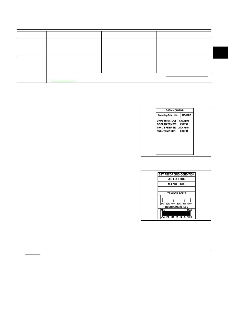
CONSULT-II has two kinds of triggers and they can be selected by touching “SETTING” in “DATA MONITOR”
mode.
1.
“AUTO TRIG” (Automatic trigger):
–
The malfunction will be identified on the CONSULT-II screen in
real time.
In other words, DTC/1st trip DTC/2nd trip DTC will be displayed
if the malfunction is detected by ECM.
At the moment a malfunction is detected by ECM, “MONITOR”
in “DATA MONITOR” screen is changed to “Recording Data ...
xx%” as shown in the figure, and the data after the malfunction
detection is recorded. Then when the percentage reached
100%, “REAL-TIME DIAG” screen is displayed. If “STOP” is
touched on the screen during “ Recording Data ... xx%”, “REAL-
TIME DIAG” screen is also displayed.
The recording time after the malfunction detection and the recording speed can be changed by “TRIG-
GER POINT” and “Recording Speed”. Refer to CONSULT-II OPERATION MANUAL.
2.
“MANU TRIG” (Manual trigger):
–
DTC/1st trip DTC/2nd trip DTC will not be displayed automati-
cally on CONSULT-II screen even though a malfunction is
detected by ECM.
DATA MONITOR can be performed continuously even though a
malfunction is detected.
Use these triggers as follows:
1.
“AUTO TRIG”
–
While trying to detect the DTC/1st trip DTC/2nd trip DTC by per-
forming the DTC Confirmation Procedure, be sure to select to
“DATA MONITOR (AUTO TRIG)” mode. You can confirm the
malfunction at the moment it is detected.
–
While narrowing down the possible causes, CONSULT-II should be set in “DATA MONITOR (AUTO
TRIG)” mode, especially in case the incident is intermittent.
When you are inspecting the circuit by gently shaking (or twisting) the suspicious connectors, components
and harness in the DTC Confirmation Procedure, the moment a malfunction is found the DTC/1st trip
DTC/2nd trip DTC will be displayed. Refer to
GI-24, "How to Perform Efficient Diagnosis for an Electrical
, “INCIDENT SIMULATION TESTS”.
2.
“MANU TRIG”
EGR VOL CONT/
V
●
Ignition switch: ON
●
Change EGR volume control
valve opening step using CON-
SULT-II.
EGR volume control valve makes
an operating sound.
●
Harness and connector
●
EGR volume control valve
PRES REGULA-
TOR
●
Ignition switch: ON
●
Change fuel rail pressure using
CONSULT-II
Fuel leaks.
●
Fuel line
●
Fuel pressure relief valve
PUMP LEANT
CLEAR
●
This mode is used for performing Fuel Pump Learning Value Clearing. Refer to
.
TEST ITEM
CONDITION
JUDGEMENT
CHECK ITEM (REMEDY)
PBIB0480E
SEF707X