Qashqai J11. Transaxle & Transmission - part 28


  Index      Nissan     Qashqai J11. Transaxle & Transmission. Service and Repair Manual


Search            copyright infringement  


Content      ..     26      27      28      29     ..


Qashqai J11. Transaxle & Transmission - part 28


TM-434

< SYSTEM DESCRIPTION >

[CVT: RE0F10G]

COMPONENT PARTS

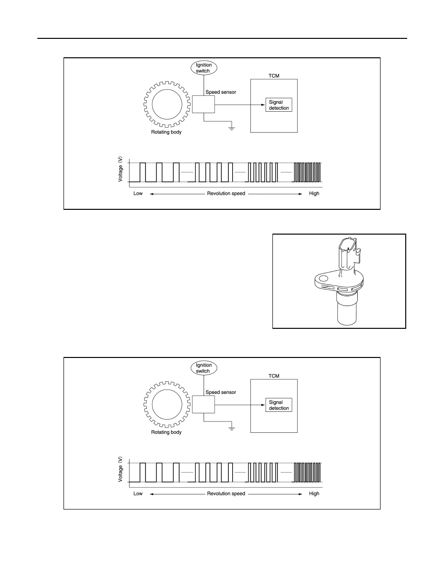
• The output speed sensor generates an ON-OFF pulse signal according to the rotating body speed. TCM

judges the rotating body speed from the pulse signal.

CVT CONTROL SYSTEM : Input Speed Sensor

INFOID:0000000010245523

• The input speed sensor is installed to the front side of transaxle

case.

• The input speed sensor detects input shaft speed. 

• The input speed sensor generates an ON-OFF pulse signal according to the rotating body speed. TCM

judges the rotating body speed from the pulse signal.

CVT CONTROL SYSTEM : CVT Fluid Temperature Sensor

INFOID:0000000010245524

• The CVT fluid temperature sensor is installed to control valve.
• The CVT fluid temperature sensor detects CVT fluid temperature in oil pan.

JSDIA1824GB

JSDIA3074ZZ

JSDIA1824GB

COMPONENT PARTS

TM-435

< SYSTEM DESCRIPTION >

[CVT: RE0F10G]

C

E

F

G

H

I

J

K

L

M

A

B

TM

N

O

P

• The fluid temperature sensor uses a thermistor, and changes the signal voltage by converting changes in the

CVT fluid temperature to a resistance value. TCM evaluates the CVT fluid temperature from the signal volt-
age value. 

CVT CONTROL SYSTEM : Primary Pressure Sensor

INFOID:0000000010245525

• The primary pressure sensor is installed to control valve.
• The primary pressure sensor detects the pressure applied to the primary pulley. 
• When pressure is applied to the ceramic device in the primary pressure sensor, the ceramic device is

deformed, resulting in voltage change. TCM evaluates the primary pressure from its voltage change. Voltage
is increased along with pressure increase. 

CVT CONTROL SYSTEM : Secondary Pressure Sensor

INFOID:0000000010245526

• The secondary pressure sensor is installed to control valve.
• The secondary pressure sensor detects the pressure applied to the secondary pulley. 

JSDIA1825GB

JSDIA1831GB

TM-436

< SYSTEM DESCRIPTION >

[CVT: RE0F10G]

COMPONENT PARTS

• When pressure is applied to the metal diaphragm in the secondary pressure sensor, the metal diaphragm is

deformed, resulting in voltage change. TCM evaluates the secondary pressure from its voltage change. Volt-
age is increased along with pressure increase. 

CVT CONTROL SYSTEM : Primary Pressure Solenoid Valve

INFOID:0000000010245527

• The primary pressure solenoid valve is installed to control valve.
• The primary pressure solenoid valve controls the primary reducing valve. For information about the primary

reducing valve, refer to 

TM-444, "TRANSAXLE : Component Description"

.

• The primary pressure solenoid valve uses the linear solenoid valve

[N/H (normal high) type].
NOTE:
• The principle of the linear solenoid valve utilizes the fact that the

force pressing on the valve spool installed inside the coil
increases nearly in proportion to the current. This allows it to pro-
duce a fluid pressure that is proportional to this pressing force.

• The N/H (normal high) produces hydraulic control when the coil

is not energized.

CVT CONTROL SYSTEM : Secondary Pressure Solenoid Valve

INFOID:0000000010245528

• The secondary pressure solenoid valve is installed to control valve.
• The secondary pressure solenoid valve controls the secondary reducing valve. For information about the

secondary reducing valve, refer to 

TM-444, "TRANSAXLE : Component Description"

.

• The secondary pressure solenoid valve uses the linear solenoid

valve [N/H (normal high) type].
NOTE:
• The principle of the linear solenoid valve utilizes the fact that the

force pressing on the valve spool installed inside the coil
increases nearly in proportion to the current. This allows it to pro-
duce a fluid pressure that is proportional to this pressing force.

• The N/H (normal high) produces hydraulic control when the coil

is not energized.

CVT CONTROL SYSTEM : Select Solenoid Valve

INFOID:0000000010245529

• The select solenoid valve is installed to control valve.
• The select solenoid valve adjusts the forward clutch engaging pressure and the reverse brake engaging

pressure. For information about the forward clutch and reverse brake, refer to 

TM-444, "TRANSAXLE :

Component Description"

.

JSDIA1831GB

JSDIA3647GB

JSDIA3647GB

COMPONENT PARTS

TM-437

< SYSTEM DESCRIPTION >

[CVT: RE0F10G]

C

E

F

G

H

I

J

K

L

M

A

B

TM

N

O

P

• The select solenoid valve uses the linear solenoid valve [N/H (nor-

mal high) type].
NOTE:
• The principle of the linear solenoid valve utilizes the fact that the

force pressing on the valve spool installed inside the coil
increases nearly in proportion to the current. This allows it to pro-
duce a fluid pressure that is proportional to this pressing force.

• The N/H (normal high) type produces hydraulic control when the

coil is not energized.

CVT CONTROL SYSTEM : Torque Converter Clutch Solenoid Valve

INFOID:0000000010245530

• The torque converter clutch solenoid valve is installed to control valve.
• The torque converter clutch solenoid valve controls the torque converter clutch control valve. For information

about the torque converter clutch control valve, refer to 

TM-444, "TRANSAXLE : Component Description"

.

• The torque converter clutch solenoid valve utilizes a linear sole-

noid valve [N/L (normal low) type].
NOTE:
• The principle of the linear solenoid valve utilizes the fact that the

force pressing on the valve spool installed inside the coil
increases nearly in proportion to the current. This allows it to pro-
duce a fluid pressure that is proportional to this pressing force.

• The N/L (normal low) type does not produce hydraulic control

when the coil is not energized.

CVT CONTROL SYSTEM : Line Pressure Solenoid Valve

INFOID:0000000010245531

• The line pressure solenoid valve is installed to control valve.
• The line pressure solenoid valve controls the pressure regulator valve. For information about the pressure

regulator valve, refer to 

TM-444, "TRANSAXLE : Component Description"

.

• The line pressure solenoid valve uses the linear solenoid valve [N/

H (normal high) type].
NOTE:
• The principle of the linear solenoid valve utilizes the fact that the

force pressing on the valve spool installed inside the coil
increases nearly in proportion to the current. This allows it to pro-
duce a fluid pressure that is proportional to this pressing force.

• The N/H (normal high) produces hydraulic control when the coil

is not energized.

CVT CONTROL SYSTEM : G SENSOR

INFOID:0000000010304575

• G sensor detects front/rear G and inclination applied to the vehicle.
• G sensor converts front/rear G and inclination applied to the vehi-

cle to voltage signal. TCM evaluates front/rear G and inclination
angle of the vehicle from the voltage signal.

JSDIA3647GB

JSDIA3648GB

JSDIA3647GB

JSDIA3076ZZ

TM-438

< SYSTEM DESCRIPTION >

[CVT: RE0F10G]

COMPONENT PARTS

CVT CONTROL SYSTEM : Electric Oil Pump

INFOID:0000000010304576

• It is operated with the signal from TCM during stop/start operation.

Oil pressure required for restart of the engine is obtained instead of
the mechanical oil pump.

• During operation, the status signal (Duty) is sent to TCM.

Electric oil pump status signal characteristics

CVT CONTROL SYSTEM : Electric Oil Pump Relay

INFOID:0000000010304577

• The electric oil pump relay is deactivated when the vehicle speed reaches 11 km/h (7 MPH) or more and

becomes activated when it reaches 6 km/h (4 MPH) or less.

• It is ON with the signal from TCM. It is ready for operation of the electric oil pump by TCM.

CVT CONTROL SYSTEM : Manual Mode Switch

INFOID:0000000010497871

• The manual mode switch 

 [mode select switch and position

select switch (upshift/downshift)] is installed in the CVT shift selec-
tor assembly.

• The mode select switch detects the position (the main shift gate

side or manual shift gate side) of the selector lever and transmits a
manual mode signal or a not manual mode signal to the combina-
tion meter. Then, the TCM receives a manual mode signal or non-
manual mode signal from the combination meter.

• The position select switch (upshift) detects that the selector lever is

shifted to the upshift side of the manual shift gate and transmits a
manual mode upshift signal to the combination meter. Then, the
TCM receives a manual mode upshift signal from the combination
meter.

• The position select switch (downshift) detects that the selector lever is shifted to the downshift side of the

manual shift gate and transmits a manual mode downshift signal to the combination meter. Then, the TCM
receives a manual mode downshift signal from the combination meter.

CVT CONTROL SYSTEM : Shift Position Indicator

INFOID:0000000010245533

TCM transmits shift position signal to combination meter via CAN communication. The actual shift position is
displayed on combination meter according to the signal.

SHIFT LOCK SYSTEM

: Electric oil pump

JSDIA5233ZZ

Status signal (Duty)

Condition

0 %

Electric oil pump power OFF

10 %

20 %

Overheat protection

30 %

In normal stop

40 %

In activation

50 %

In normal operation

60 – 100 %

Possible malfunction

JSDIA5308ZZ

COMPONENT PARTS

TM-439

< SYSTEM DESCRIPTION >

[CVT: RE0F10G]

C

E

F

G

H

I

J

K

L

M

A

B

TM

N

O

P

SHIFT LOCK SYSTEM : Component Parts Location

INFOID:0000000010245534

SHIFT LOCK SYSTEM : Park Position Switch

INFOID:0000000010245535

The park position switch detects that the selector lever is in “P” position.

SHIFT LOCK SYSTEM : Shift Lock Solenoid

INFOID:0000000010245536

The shift lock solenoid operates according to the signal from the BCM and moves the lock lever. For shift lock
operation, refer to 

TM-445, "SHIFT LOCK SYSTEM : System Description"

.

SHIFT LOCK SYSTEM : Stop Lamp Switch

INFOID:0000000010245537

• The stop lamp switch turns ON when the brake pedal is depressed.
• When the stop lamp switch turns ON, the BCM is energized.

CVT shift selector assembly

Brake pedal, upper

No.

Component

Function

Shift lock solenoid

TM-439, "SHIFT LOCK SYSTEM : Shift Lock Solenoid"

Park position switch

TM-439, "SHIFT LOCK SYSTEM : Park Position Switch"

Stop lamp switch

TM-439, "SHIFT LOCK SYSTEM : Stop Lamp Switch"

JSDIA5309ZZ

TM-440

< SYSTEM DESCRIPTION >

[CVT: RE0F10G]

STRUCTURE AND OPERATION

STRUCTURE AND OPERATION

TRANSAXLE

TRANSAXLE : Cross-Sectional View

INFOID:0000000010245538

Converter housing 

Oil pump

Planetary gear

Control valve

Oil pan

Chain belt 

Primary pulley

Secondary pulley

Side cover

Transaxle case

Differential case

Final gear

Reduction gear

Idler gear

Output gear

Drive sprocket 

Torque converter

Driven sprocket

Oil pump chain 

JSDIA3719ZZ

STRUCTURE AND OPERATION

TM-441

< SYSTEM DESCRIPTION >

[CVT: RE0F10G]

C

E

F

G

H

I

J

K

L

M

A

B

TM

N

O

P

TRANSAXLE : Operation Status

INFOID:0000000010245539

×

: Engaged or applied.

TRANSAXLE : Transaxle Mechanism

INFOID:0000000010245540

TORQUE CONVERTER (WITH LOCK-UP FUNCTION)

In the same way as a conventional A/T, the torque converter is a system that increases the engine torque and
transmits the torque to the transaxle. A symmetrical 3-element, 1-stage, 2-phase type is used here.

OIL PUMP

Utilizes a vane-type oil pump that is driven by the engine through the oil pump drive chain in order to increase
efficiency of pump discharge volume in low-speed zone and optimize pump discharge volume in high-speed
zone. Discharged oil from oil pump is transmitted to control valve. It is used as the oil of primary and second-
ary pulley operation, the oil of clutch operation, and the lubricant for each part.

PLANETARY GEAR

• A planetary gear type of forward/reverse selector mechanism is installed between the torque converter and

primary pulley.

• The power from the torque converter is input via the input shaft, operating a wet multi-plate clutch by means

of hydraulic pressure to switch between forward and reverse driving.

Operation of Planetary gear

BELT & PULLEY

It is composed of a pair of pulleys (the groove width is changed freely in the axial direction) and the chain belt
.The groove width changes according to wrapping radius of chain belt and pulley from low status to overdrive
status continuously with non-step. It is controlled with the oil pressures of primary pulley and secondary pulley.

Chain belt

Selector lever 

position

Parking mech-

anism

Forward 

clutch

Reverse brake 

Primary pulley 

Secondary 

pulley

Steel belt

Final drive

P

×

R

×

×

×

×

×

N

D

×

×

×

×

×

Ds

×

×

×

×

×

JSDIA2426GB

TM-442

< SYSTEM DESCRIPTION >

[CVT: RE0F10G]

STRUCTURE AND OPERATION

The chain belt consists of approximately 150 locker pins 

 and

1,000 link plates 

. Chains are rotated by locker pins sandwiched by

pulleys. This produces tension difference in chains among pulleys.
Accordingly, the power is transferred by the tension.

Pulley

The primary pulley (input shaft side) and the secondary pulley (output shaft side) have the shaft with slope
(fixed cone surface), movable sheave (movable cone surface that can move in the axial direction) and oil pres-
sure chamber at the back of the movable sheave. 
The movable sheave slides on the shaft to change the groove width of the pulley. Input signals of engine load
(accelerator pedal opening), primary pulley speed and secondary pulley speed change the operation pres-
sures of the primary pulley and the secondary pulley, and controls the pulley groove width. 

FINAL DRIVE AND DIFFERENTIAL

JSDIA3643ZZ

JSDIA2429GB

STRUCTURE AND OPERATION

TM-443

< SYSTEM DESCRIPTION >

[CVT: RE0F10G]

C

E

F

G

H

I

J

K

L

M

A

B

TM

N

O

P

The deceleration gears are composed of 2 stages: primary deceleration (output gear, idler gear pair) and sec-
ondary deceleration (reduction gear, final gear pair). All of these gears are helical gears.
The lubrication oil is the same as the CVT fluid which lubricates the entire transaxle.

TRANSAXLE : Oil Pressure System 

INFOID:0000000010245541

Oil pressure required for operation of the transaxle transmission mechanism is generated by oil pump, oil
pressure control valve, solenoid valve, etc. During idling stop, the electric oil pump is activated to generate oil
pressure required for restarting the engine.

JSDIA2427GB

JSDIA5339GB

TM-444

< SYSTEM DESCRIPTION >

[CVT: RE0F10G]

STRUCTURE AND OPERATION

TRANSAXLE : Component Description

INFOID:0000000010245542

FLUID COOLER & FLUID WARMER SYSTEM

Part name

Function

Torque converter

Increases engine torque and transmits it to the transaxle.

Oil pump

Utilizes a vane-type oil pump that is driven by the engine through the oil pump drive chain in order to 
increase efficiency of pump discharge volume in low-speed zone and optimize pump discharge volume 
in high-speed zone. Discharged oil from oil pump is transmitted to control valve. It is used as the oil of 
primary and secondary pulley operation, the oil of clutch operation, and the lubricant for each part.

Forward clutch

The forward clutch is wet and multiple plate type clutch that consists of clutch drum, piston, drive plate, 
and driven plate. It is a clutch to move the vehicle forward by activating piston hydraulically, engaging 
plates, and directly connecting sun gear and input shaft.

Reverse brake

The reverse brake is a wet multiple-plate type brake that consists of transaxle case, piston, drive plate, 
and driven plate. It is a brake to move the vehicle in reverse by activating piston hydraulically, engaging 
plates, and fixing planetary gear.

Internal gear

The internal gear is directly connected to forward clutch drum. It is a gear that moves the outer edge of 
pinion planet of planet carrier. It transmits power to move the vehicle in reverse when the planet carrier 
is fixed.

Planet carrier

Composed of a carrier, pinion planet, and pinion shaft. This gear fixes and releases the planet carrier in 
order to switch between forward and reverse driving.

Sun gear

Sun gear is a set part with planet carrier and internal gear. It transmits transmitted force to primary fixed 
sheave. It rotates in forward or reverse direction according to activation of either forward clutch or re-
verse brake.

Input shaft

The input shaft is directly connected to forward clutch drum and transmits traction force from torque con-
verter. In shaft center, there are holes for hydraulic distribution to primary pulley and hydraulic distribution 
for lockup ON/OFF.

Primary pulley

It is composed of a pair of pulleys (the groove width is changed freely in the axial direction) and the chain 
belt. The groove width changes according to wrapping radius of steel belt and pulley from low status to 
overdrive status continuously with non-step. It is controlled with the oil pressures of primary pulley and 
secondary pulley.

Secondary pulley

Chain belt

Manual shaft

When the manual shaft is in the P position, the parking rod that is linked to the manual shaft rotates the 
parking pole. When the parking pole rotates, it engages with the parking gear, fixing the parking gear. As 
a result, the secondary pulley that is integrated with the parking gear is fixed.

Parking rod

Parking pawl

Parking gear

Output gear

The deceleration gears are composed of 2 stages: primary deceleration (output gear, idler gear pair) and 
secondary deceleration (reduction gear, final gear pair). All of these gears are helical gears.

Idler gear

Reduction gear

Differential 

Torque converter regulator 
valve

Adjusts the feed pressure to the torque converter to the optimum pressure corresponding to the driving 
condition.

Pressure regulator valve

Adjusts the discharge pressure from the oil pump to the optimum pressure (line pressure) corresponding 
to the driving condition.

Torque converter clutch 
control valve

Adjusts the torque converter engage and disengage pressures.

Manual valve

Distributes the clutch operation pressure to each circuit according to the selector lever position.

Secondary reducing valve

Reduces line pressure and adjusts secondary pressure.

Primary reducing valve

Reduces line pressure and adjusts primary pressure.

Pilot valve A

Reduces line pressure and adjusts pilot pressure to the solenoid valves listed below.
• Primary pressure solenoid valve
• Secondary pressure solenoid valve
• Select solenoid valve
• Line pressure solenoid valve

Pilot valve B

Reduces pilot pressure and adjusts pilot pressure to the torque converter clutch solenoid valve.

STRUCTURE AND OPERATION

TM-445

< SYSTEM DESCRIPTION >

[CVT: RE0F10G]

C

E

F

G

H

I

J

K

L

M

A

B

TM

N

O

P

FLUID COOLER & FLUID WARMER SYSTEM : System Description

INFOID:0000000010245543

CVT FLUID COOLER SCHEMATIC

COMPONENT DESCRIPTION

CVT Oil Warmer

• The CVT oil warmer 

 is installed on the front part of transaxle

assembly.

• When engine is started while engine and CVT are cold, engine

coolant temperature rises more quickly than CVT fluid tempera-
ture. CVT oil warmer is provided with two circuits for CVT and
engine coolant respectively so that warmed engine coolant warms
CVT quickly. This helps shorten CVT warming up time, improving
fuel economy.

• A cooling effect is obtained when CVT fluid temperature is high.

CVT Fluid Cooler

• The CVT fluid cooler 

 is installed to the vehicle front.

• CVT fluid is cooled by driving blast while driving the vehicle.

SHIFT LOCK SYSTEM

SHIFT LOCK SYSTEM : System Description

INFOID:0000000010245544

• The shift lock system prevents the select lever from being moved from “P” position to other positions due to

a driver's improper operation and prevents the occurrence of an abrupt start.

• Shift lock can be released when the following conditions are satisfied.
- Ignition switch is ON.
- Brake pedal is depressed. (Stop lamp switch is ON)

SHIFT LOCK OPERATION AT P POSITION

When brake pedal is not depressed (no selector operation allowed)

JSDIA5444GB

JSDIA5170ZZ

JSDIA5255ZZ

TM-446

< SYSTEM DESCRIPTION >

[CVT: RE0F10G]

STRUCTURE AND OPERATION

When the brake pedal is not depressed with the ignition switch ON,
the shift lock solenoid 

 is OFF (not energized) and the solenoid rod

 is extended with spring.

The connecting lock lever 

 is located at the position shown in the

figure when the solenoid rod is extended. It prevents the movement
of the detent rod 

. The selector lever cannot be shifted from the “P”

position for this reason.

When brake pedal is depressed (selector lever operation allowed)

The shift lock solenoid 

 is turned ON (energized) when the brake

pedal is depressed with the ignition switch ON. The solenoid rod 
is compressed with the electromagnetic force. The connecting lock
lever 

 rotates when the solenoid rod is compressed. Therefore, the

detent rod 

 can be moved. The selector lever can be shifted to

other positions for this reason.

FORCIBLE RELEASE OF SHIFT LOCK

• When battery voltage decreases or an electrical/mechanical mal-

function occurs in the shift lock system, the selector lever cannot
be operated in “P” position. When shift lock release rod 

 is

pressed in this state, lock lever 

 is forcibly rotated, and then it

becomes possible to release shift lock.

• To release the shift lock forcibly and shift the selector lever from “P” position to other positions, follow the

steps below.

1.

Turn ignition switch OFF.

2.

Apply parking brake.

3.

Press the shift lock release button 

 with suitable tool.

4.

Press and hold the selector lever knob button and move the
selector lever from “P” position to other positions while press the
shift lock release button.

KEY LOCK SYSTEM

KEY LOCK SYSTEM : System Description

INFOID:0000000010360483

KEY LOCK MECHANISM

The key is not set to LOCK when the selector lever is not selected to P position. This prevents the key from
being removed from the key cylinder.

JSDIA2817ZZ

JSDIA2818ZZ

: Shift lock solenoid

: Detent rod

JSDIA2819ZZ

JSDIA5409ZZ

STRUCTURE AND OPERATION

TM-447

< SYSTEM DESCRIPTION >

[CVT: RE0F10G]

C

E

F

G

H

I

J

K

L

M

A

B

TM

N

O

P

Key lock status

The slider 

 in the key cylinder 

 is moved to the left side of the fig-

ure when the selector lever is in any position other than P position.
The rotator 

 that rotates together with the key 

 cannot be rotated

for this reason. The key cannot be removed from the key cylinder
because it cannot be turned to LOCK 

.

Key unlock status

The slider 

 in the key cylinder 

 is moved to the right side of the

figure when the selector lever is in P position and the finger is
removed from the selector button. The rotator 

 can be rotated for

this reason. The key 

 can be removed from the key cylinder

because it can be turned to LOCK 

.

JPDIA0108ZZ

JPDIA0109ZZ

TM-448

< SYSTEM DESCRIPTION >

[CVT: RE0F10G]

SYSTEM

SYSTEM

CVT CONTROL SYSTEM

CVT CONTROL SYSTEM : System Description

INFOID:0000000010245545

SYSTEM DIAGRAM

MAIN CONTROL CONTENTS OF TCM

JSDIA5340GB

Controls

Reference

Line pressure control

TM-455, "LINE PRESSURE CONTROL : System Description"

Shift control

TM-455, "SHIFT CONTROL : System Description"

Select control

TM-459, "SELECT CONTROL : System Description"

Lock-up control

TM-459, "LOCK-UP CONTROL : System Description"

ECO mode control

DMS-6, "ECO MODE CONTROL : System Description"

Stop/start system

TM-461, "STOP/START SYSTEM : System Description"

Fail-safe

TM-478, "Fail-safe"

Self-diagnosis function

TM-466, "CONSULT Function"

Communication function with CONSULT

TM-466, "CONSULT Function"

SYSTEM

TM-449

< SYSTEM DESCRIPTION >

[CVT: RE0F10G]

C

E

F

G

H

I

J

K

L

M

A

B

TM

N

O

P

LIST OF CONTROL ITEMS AND INPUT/OUTPUT

*: If these input/output signals show errors, TCM activates the fail-safe function.

CVT CONTROL SYSTEM : Fail-safe

INFOID:0000000010354549

TCM has a fail-safe mode. The mode functions so that operation can be continued even if the signal circuit of
the main electronically controlled input/output parts is damaged.
If the vehicle shows following behaviors including “poor acceleration”, a malfunction of the applicable system
is detected by TCM and the vehicle may be in a fail-safe mode. At this time, check the DTC code and perform
inspection and repair according to the malfunction diagnosis procedures. 

Fail-safe function

Control Item

Shift control

Line pressure 

control

Select control

Lock-up con-

trol

Fail-safe func-

tion

*

Input

Engine torque signal
(CAN communication)

×

×

×

×

×

Engine speed signal
(CAN communication)

×

×

×

×

×

Accelerator pedal position signal
(CAN communication)

×

×

×

×

Idle signal
(CAN communication)

×

×

×

Closed throttle position signal
(CAN communication)

×

×

×

Stop lamp switch signal
(CAN communication)

×

×

×

×

Primary pressure sensor

×

Secondary pressure sensor 

×

×

×

CVT fluid temperature sensor

×

×

×

×

×

Primary speed sensor

×

×

×

×

×

Output speed sensor

×

×

×

×

Input speed sensor

×

×

×

×

×

Transmission range switch

×

×

×

×

×

Output

Line pressure solenoid valve

×

×

×

×

Primary pressure solenoid valve

×

×

×

Torque converter clutch solenoid 
valve

×

×

Secondary pressure solenoid valve

×

×

×

Select solenoid valve

×

×

×

Shift position indicator
(CAN communication)

×


Content      ..     26      27      28      29     ..