Qashqai J11. Charging system - part 3
CHG
ALTERNATOR
CHG-31
< REMOVAL AND INSTALLATION >
[TYPE 1]
C
D
E
F
G
H
I
J
K
L
B
A
O
P
N
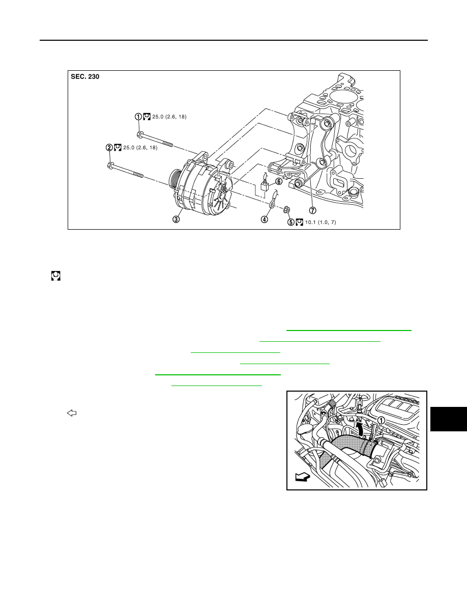
R9M : Exploded View
INFOID:0000000010323930
R9M : Removal and Installation
INFOID:0000000010323931
REMOVAL
1.
Disconnect the battery cable from the negative terminal. Refer to
PG-155, "Removal and Installation"
2.
Remove wheel nuts, and then tire assembly RH. Refer to
WT-60, "Removal and Installation"
.
3.
Remove engine under cover. Refer to
.
4.
Remove front fender protector RH partially. Refer to
.
5.
Remove drive belt. Refer to
EM-373, "Removal and Installation"
6.
Remove air duct (inlet). Refer to
.
7.
Get air inlet hose 1 (1) out of alternator removal area.
8.
Remove solenoid valve and bracket assembly.
1.
Alternator mounting bolt (upper)
2.
Alternator mounting bolt (lower)
3.
Alternator
4.
“B” terminal harness
5.
“B” terminal nut
6.
Alternator connector
7.
Alternator bracket
: N·m (kg-m, ft-lb)
JMMIA0962GB
: Vehicle front
JMMIA0963ZZ