Nissan Qashqai J11. Manual - part 755
P2765 INPUT SPEED SENSOR B
TM-595
< DTC/CIRCUIT DIAGNOSIS >
[CVT: RE0F10G]
C
E
F
G
H
I
J
K
L
M
A
B
TM
N
O
P
YES
>> GO TO 4.
NO
>> Repair or replace malfunctioning parts.
4.
CHECK CIRCUIT BETWEEN OUTPUT SPEED SENSOR AND TCM (PART 2)
Check continuity between output speed sensor harness connector terminal and ground.
Is the inspection result normal?
YES
>> GO TO 5.
NO
>> Repair or replace malfunctioning parts.
5.
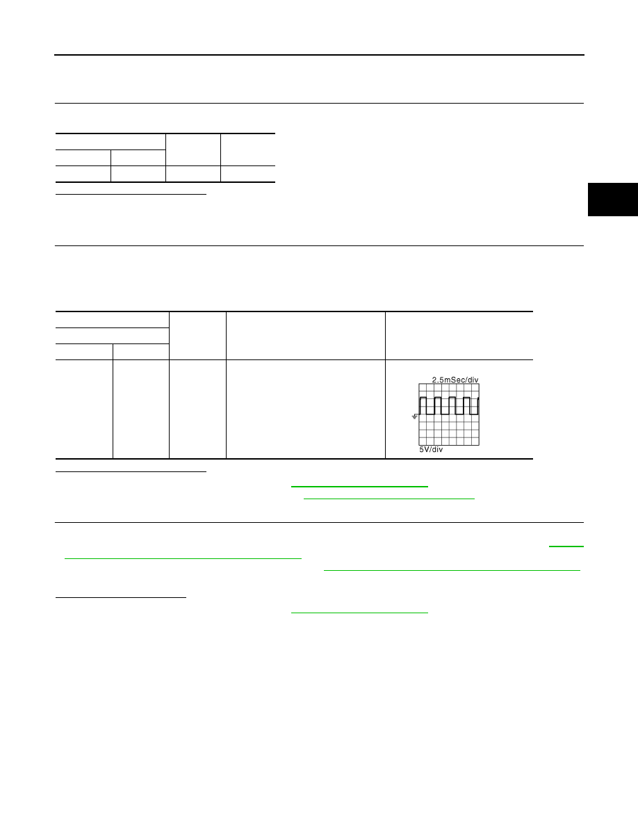
CHECK TCM INPUT SIGNALS
1.
Connect all of disconnected connectors.
2.
Lift the vehicle.
3.
Start the engine.
4.
Check frequency of output speed sensor.
Is the inspection result normal?
YES
>> Check intermittent incident. Refer to
GI-41, "Intermittent Incident"
.
NO
>> Replace output speed sensor. Refer to
TM-636, "Removal and Installation"
.
6.
DETECT MALFUNCTIONING ITEMS
Check the following items:
• Open circuit or short circuit in harness between ignition switch and output speed sensor. Refer to
"Wiring Diagram - IGNITION POWER SUPPLY -"
.
• 10A fuse [No.74, located in fuse block (J/B)]. Refer to
PG-97, "Fuse, Connector and Terminal Arrangement"
.
• IPDM E/R
Is the check result normal?
YES
>> Check intermittent incident. Refer to
GI-41, "Intermittent Incident"
.
NO
>> Repair or replace malfunctioning parts.
Output speed sensor
—
Continuity
Connector
Terminal
F41
2
Ground
Not existed
+
−
Condition
Frequency
(Approx.)
TCM
Connector
Terminal
F1
34
Ground
• Shift position: “M1” position
• Vehicle speed: 20 km/h (12 MPH)
200 Hz
JSDIA1904GB