Nissan Qashqai J11. Manual - part 574
FUEL TANK
FL-41
< REMOVAL AND INSTALLATION >
[K9K]
C
D
E
F
G
H
I
J
K
L
M
A
FL
N
P
O
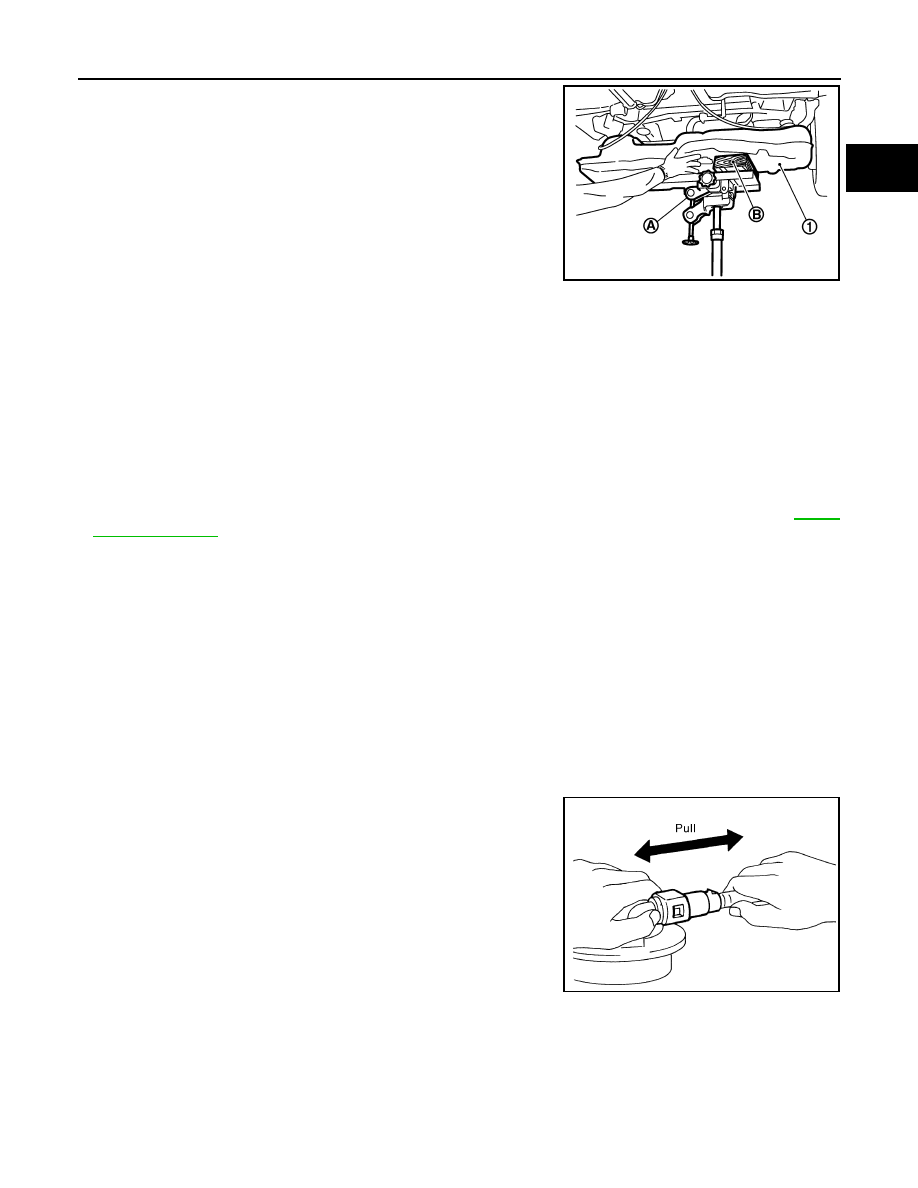
7.
Support center of fuel tank (1) with transmission jack (A) and
piece of wood (B).
CAUTION:
• Make sure the tank bottom surface is supported well
enough to prevent an unstable condition when lowering
the tank.
• Make sure to hold it securely as tank surface may not be
flat.
8.
Remove fuel tank band (RH and LH).
9.
Lower transmission jack carefully to remove fuel tank while holding it by hand.
CAUTION:
Make sure to avoid any interference with surrounding component that may cause damage.
INSTALLATION
Note the following, and install in the reverse order of removal.
CAUTION:
• Make sure hose clamps and hoses clips are not secured on top of the filler tube bulges.
• Make sure all quick connectors and their mating part are free of foreign matter, check for damage.
• Ensure the tank bands are correctly assembled as per their identification marks "L" and "R".
• Make sure that the torques of the mounting bolts are correct as per exploded view. Refer to
.
• Make sure that when installing the connectors, the confirmation click sound is heard. Pull back on
the connector to ensure proper engagement.
Fuel Filler Hose
• Insert fuel filler hose to the length below.
• Be sure hose clamp is not placed on swelled area of fuel filler tube.
• Tighten fuel filler hose clamp so that the remaining length of screw thread becomes to the following.
EVAP Hose
1.
Check connections for damage or foreign material.
2.
Align the matching side connection part with the center of shaft,
and insert connector straight until it clicks.
3.
After connecting, pull out quick connector and centralized under-
floor piping by hand. Make sure connections are secure.
Inspection
INFOID:0000000010419004
INSPECTION AFTER INSTALLATION
Make sure there is no fuel leakage at connections in the following procedure.
• Start engine, rev it up and make sure there is no fuel leakage at connections.
PBIC3792E
: 35 mm (1.38 in)
Fuel filler tube side
: 7 - 11 mm (0.28 - 0.43 in)
Fuel tank side
: 5 - 9 mm (0.20 - 0.35 in)
PBIC1653E