Nissan Qashqai J11. Manual - part 513
 

  Index      Nissan     Nissan Qashqai J11 - Service and Repair Manual


Search            


Content   ..  511  512  513  514   ..


Nissan Qashqai J11. Manual - part 513


EC9-208

< DTC/CIRCUIT DIAGNOSIS >

[R9M]

P0135 A/F SENSOR HEATER

YES

>> GO TO 4.

NO

>> Repair or replace error-detected parts.

4.

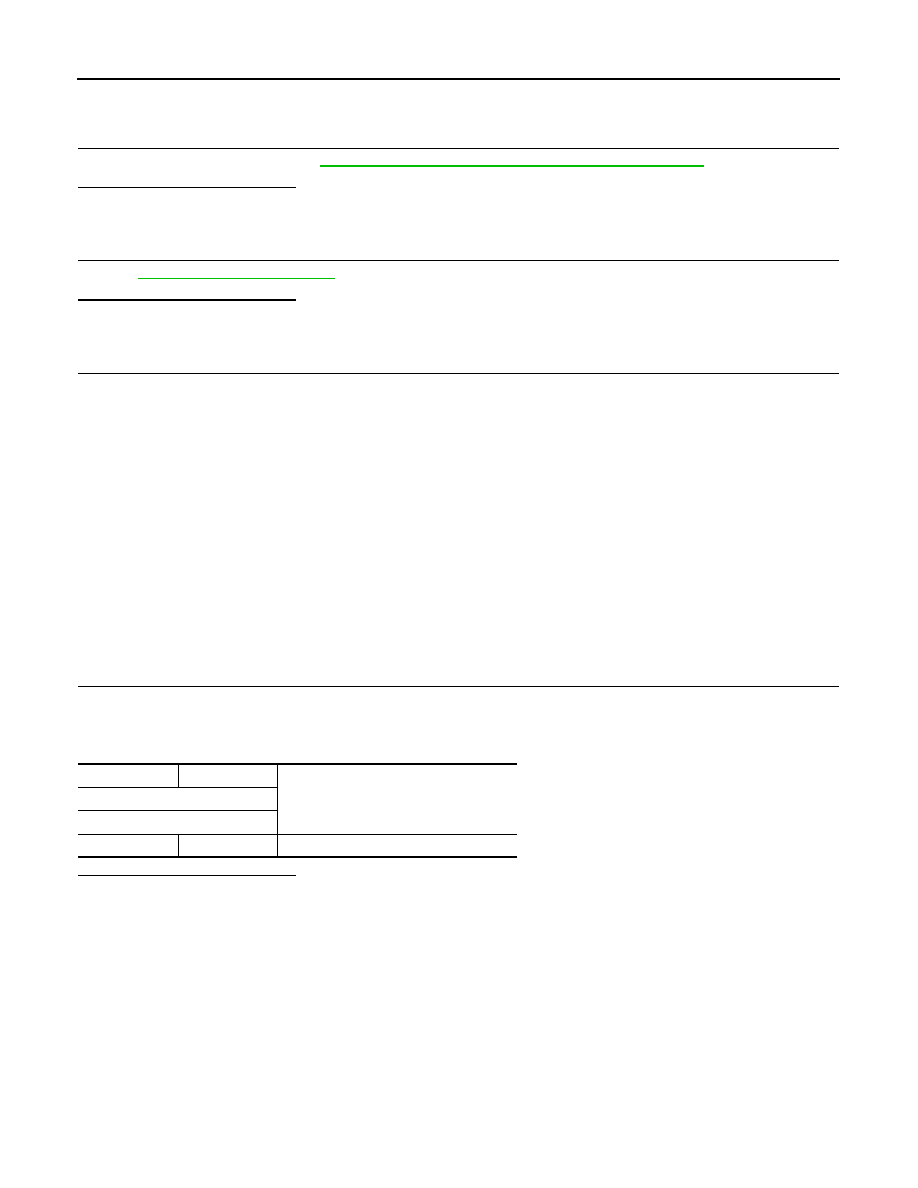
CHECK A/F SENSOR HEATER

Check A/F sensor heater. Refer to 

EC9-208, "Component Inspection (A/F Sensor Heater)"

.

Is the inspection result normal?

YES

>> GO TO 5.

NO

>> GO TO 6.

5.

CHECK INTERMITTENT INCIDENT

Perform 

GI-41, "Intermittent Incident"

.

Is the inspection result normal?

YES

>> GO TO 6.

NO

>> Repair or replace error-detected parts.

6.

REPLACE A/F SENSOR

Replace A/F sensor.

CAUTION:

• Discard any A/F sensor which has been dropped from a height of more than 0.5 m (19.7 in) onto a

hard surface such as a concrete floor; use a new one.

• Before installing new A/F sensor, clean exhaust system threads using Heated Oxygen Sensor

Thread Cleaner tool and approved anti-seize lubricant.

>> INSPECTION END

Component Inspection (A/F Sensor Heater)

INFOID:0000000010501521

CAUTION:

• Discard any air fuel ratio (A/F) sensor which has been dropped from a height of more than 0.5 m

(19.7 in) onto a hard surface such as a concrete floor; use a new one.

• Before installing new air fuel ratio (A/F) sensor, clean exhaust system threads using Heated Oxygen

Sensor Thread Cleaner tool and approved anti-seize lubricant.

1.

CHECK AIR FUEL RATIO (A/F) SENSOR

1.

Turn ignition switch OFF.

2.

Disconnect A/F sensor harness connector.

3.

Check the resistance between A/F sensor terminals.

Is the inspection result normal?

YES

>> INSPECTION END

NO

>> Replace malfunctioning air fuel ratio (A/F) sensor.

+

Resistance

A/ F sensor

Terminal

3

4

2.4 - 4.0 

 [at 25

°

C (77

°

F)]

P0190 FRP SENSOR

EC9-209

< DTC/CIRCUIT DIAGNOSIS >

[R9M]

C

D

E

F

G

H

I

J

K

L

M

A

EC9

N

P

O

P0190 FRP SENSOR

DTC Logic

INFOID:0000000010309135

DTC DETECTION LOGIC

NOTE:
If DTC P0190 is displayed with DTC P0697, first perform the trouble diagnosis for DTC P0697. Refer to

EC9-271, "DTC Logic"

.

DTC CONFIRMATION PROCEDURE

1.

PERFORM DIAGNOSIS PROCEDURE

NOTE:
DTC P0190 can not duplicate.

>> Proceed to 

EC9-209, "Diagnosis Procedure"

.

Diagnosis Procedure

INFOID:0000000010309136

1.

CHECK ECM HARNESS CONNECTOR CONNECTIONS

1.

Turn ignition switch OFF.

2.

Check ECM harness connector connection.

Is the inspection result normal?

YES

>> GO TO 2.

NO

>> Repair or replace error-detected parts.

2.

CHECK FUEL RAIL PRESSURE SENSOR HARNESS CONNECTOR CONNECTIONS

Check fuel rail pressure sensor harness connector connection.

Is the inspection result normal?

YES

>> GO TO 3.

NO

>> Repair or replace error-detected parts.

3.

CHECK FUEL PIPING

Check fuel hoses and fuel tubes for clogging.
Is the inspection result normal?

YES

>> GO TO 4.

NO

>> Repair or replace error-detected parts.

4.

CHECK FUEL RAIL PRESSURE SENSOR POWER SUPPLY CIRCUIT

1.

Turn ignition switch ON.

2.

Check the power supply of the fuel rail pressure sensor.

DTC No.

CONSULT screen terms

(Trouble diagnosis content)

DTC detecting condition

Possible cause

P0190

RAIL PRESSURE SENSOR 
CIRCUIT
(Fuel rail pressure sensor “A” 
circuit)
• 1.DEF: VOLTAGE TOO LOW
• 2.DEF: VOLTAGE TOO HIGH
• 3.DEF: ABOVE THE MAX 

LEVEL

• An excessively low voltage from the 

sensor is sent to ECM.

• An excessively high voltage from the 

sensor is sent to ECM.

• An improper voltage signal from sen-

sor is sent to ECM.

• Harness or connectors

(Fuel rail pressure sensor circuit is open or 
shorted.)

• Fuel rail pressure sensor

+

-

Voltage

(Approx.)

Fuel rail pressure sensor

Connector

Terminal

F86

91

Ground

5.0 V

EC9-210

< DTC/CIRCUIT DIAGNOSIS >

[R9M]

P0190 FRP SENSOR

Is the inspection result normal?

YES

>> GO TO 5.

NO

>> Perform trouble diagnosis for power supply circuit.

5.

CHECK FUEL RAIL PRESSURE SENSOR CIRCUIT FOR OPEN AND SHORT

1.

Turn ignition switch OFF.

2.

Check fuel rail pressure sensor circuit for open and short.

Is the inspection result normal?

YES

>> Replace fuel rail pressure sensor.

NO

>> Repair or replace error-detected parts.

+

-

Continuity

ECM

Fuel rail pressure sensor

Connector

Terminal

Connector

Terminal

F82

73

F86

1

Existed

77

2

91

3

P0200 FUEL INJECTOR

EC9-211

< DTC/CIRCUIT DIAGNOSIS >

[R9M]

C

D

E

F

G

H

I

J

K

L

M

A

EC9

N

P

O

P0200 FUEL INJECTOR

DTC Logic

INFOID:0000000010309137

DTC DETECTION LOGIC

DTC CONFIRMATION PROCEDURE

1.

PRECONDITIONING

If DTC Confirmation Procedure has been previously conducted, always turn ignition switch OFF and wait at
least 1 minute before conducting the next test.

>> GO TO 2.

2.

PERFORM DTC CONFIRMATION PROCEDURE

1.

Start engine and let it idle for at least 1 second.

2.

Check DTC.

Is DTC detected?

YES

>>

EC9-211, "Diagnosis Procedure"

.

NO

>> INSPECTION END

Diagnosis Procedure

INFOID:0000000010309138

1.

CHECK FUEL INJECTOR HARNESS CONNECTOR STATE

Check fuel injector harness connector state.

Is the inspection result normal?

YES

>> GO TO 2.

NO

>> Repair or replace error-detected parts.

2.

CHECK FUEL INJECTOR

Refer to 

EC9-212, "Component Inspection (Fuel Injector)"

.

Is the inspection result normal?

YES

>> GO TO 3.

NO

>> Replace malfunctioning injector(s).

3.

CHECK FUEL INJECTOR CIRCUIT FOR OPEN AND SHORT

1.

Turn ignition switch OFF.

2.

Disconnect ECM harness connector.

3.

Check fuel injector circuit for open and short.

DTC No.

CONSULT screen terms

(Trouble diagnosis content)

DTC detecting condition

Possible Cause

P0200

INJECTOR CONTROL 
CIRCUIT
(Injector circuit/open)
• 1.DEF: VALUES OUT-

SIDE TOLERANCES

• ECM detects fuel injectors circuit malfunction.
• Injector code is not stored into ECM.

• Harness or connectors
• Injector code error


Content   ..  511  512  513  514   ..