Nissan Qashqai J11. Manual - part 270
DIAGNOSIS SYSTEM (ECM)
ECM-57
< SYSTEM DESCRIPTION >
[MR20DD]
C
D
E
F
G
H
I
J
K
L
M
A
ECM
N
P
O
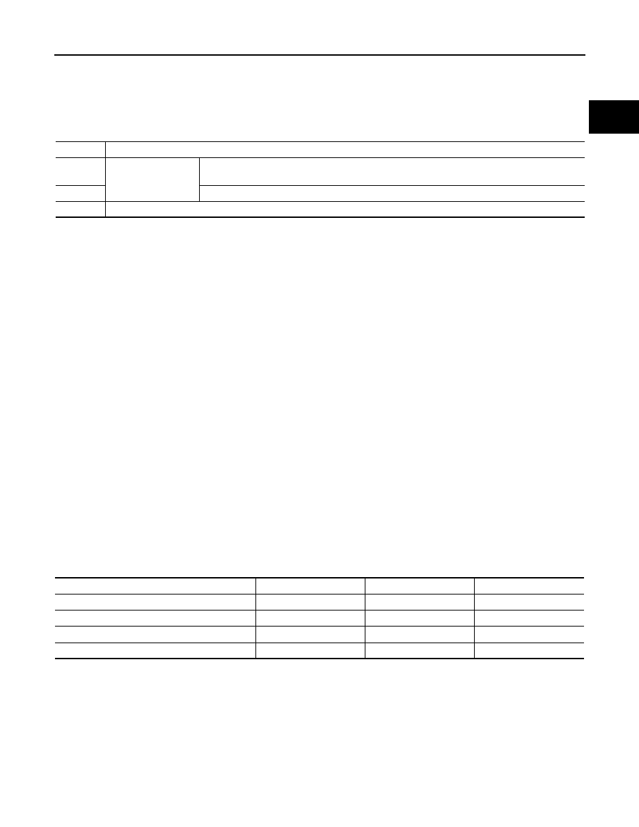
Only one set of freeze frame data (either 1st trip freeze frame data or freeze frame data) can be stored in the
ECM. 1st trip freeze frame data is stored in the ECM memory along with the 1st trip DTC. There is no priority
for 1st trip freeze frame data and it is updated each time a different 1st trip DTC is detected. However, once
freeze frame data (2nd trip detection/MIL on) is stored in the ECM memory, 1st trip freeze frame data is no
longer stored. Remember, only one set of freeze frame data can be stored in the ECM. The ECM has the fol-
lowing priorities to update the data.
For example, the EGR malfunction (Priority: 2) was detected and the freeze frame data was saved in the 2nd
trip. After that when the misfire (Priority: 1) is detected in another trip, the freeze frame data will be updated
from the EGR malfunction to the misfire. The 1st trip freeze frame data is updated each time a different mal-
function is detected. There is no priority for 1st trip freeze frame data. However, once freeze frame data is
stored in the ECM memory, 1st trip freeze data is no longer stored (because only one freeze frame data or 1st
trip freeze frame data can be stored in the ECM). If freeze frame data is stored in the ECM memory and freeze
frame data with the same priority occurs later, the first (original) freeze frame data remains unchanged in the
ECM memory.
Both 1st trip freeze frame data and freeze frame data (along with the DTCs) are cleared when the ECM mem-
ory is erased.
DIAGNOSIS DESCRIPTION : Counter System
INFOID:0000000010702843
RELATIONSHIP BETWEEN MIL, 1ST TRIP DTC, DTC, AND DETECTABLE ITEMS
• When a malfunction is detected for the first time, the 1st trip DTC and the 1st trip freeze frame data are
stored in the ECM memory.
• When the same malfunction is detected in two consecutive trips, the DTC and the freeze frame data are
stored in the ECM memory, and the MIL will come on.
• The MIL will turn OFF after the vehicle is driven 3 times (driving pattern B) with no malfunction. The drive is
counted only when the recorded driving pattern is met (as stored in the ECM). If another malfunction occurs
while counting, the counter will reset.
• The DTC and the freeze frame data will be stored until the vehicle is driven 40 times (driving pattern A) with-
out the same malfunction recurring (except for Misfire and Fuel Injection System). For Misfire and Fuel Injec-
tion System, the DTC and freeze frame data will be stored until the vehicle is driven 80 times (driving pattern
C) without the same malfunction recurring. The “TIME” in “SELF-DIAGNOSTIC RESULTS” mode of CON-
SULT will count the number of times the vehicle is driven.
• The 1st trip DTC is not displayed when the self-diagnosis results in OK for the 2nd trip.
COUNTER SYSTEM CHART
For details about patterns B and C under “Fuel Injection System” and “Misfire”, see “EXPLANATION FOR
DRIVING PATTERNS FOR “MISFIRE <EXHAUST QUALITY DETERIORATION>”, “FUEL INJECTION SYS-
TEM”.
For details about patterns A and B under Other, see “EXPLANATION FOR DRIVING PATTERNS FOR “MIS-
FIRE <EXHAUST QUALITY DETERIORATION>”, “FUEL INJECTION SYSTEM”.
• *1: Clear timing is at the moment OK is detected.
• *2: Clear timing is when the same malfunction is detected in the 2nd trip.
Relationship Between MIL, DTC, 1st Trip DTC and Driving Patterns for “Misfire <Exhaust Quality De-
terioration>”, “Fuel Injection System”
Priority
Items
1
Freeze frame data
Misfire — DTC: P0300 – P0304
Fuel Injection System Function — DTC: P0171, P0172
2
Except the above items
3
1st trip freeze frame data
Items
Fuel Injection System
Misfire
Other
MIL (turns OFF)
3 (pattern B)
3 (pattern B)
3 (pattern B)
DTC, Freeze Frame Data (no display)
80 (pattern C)
80 (pattern C)
40 (pattern A)
1st Trip DTC (clear)
1 (pattern C), *1
1 (pattern C), *1
1 (pattern B)
1st Trip Freeze Frame Data (clear)
*1, *2
*1, *2
1 (pattern B)