Nissan Qashqai J11. Manual - part 2081


  Index      Nissan     Nissan Qashqai J11 - Service and Repair Manual


Search            


Content   ..  2079  2080  2081  2082   ..


Nissan Qashqai J11. Manual - part 2081


AV

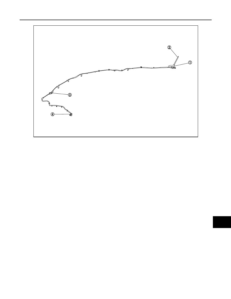
COMPONENT PARTS

AV-13

< SYSTEM DESCRIPTION >

[AUDIO SYSTEM]

C

D

E

F

G

H

I

J

K

L

M

B

A

O

P

1.

Antenna base (antenna amp. and 
satellite antenna)

2.

Rod Antenna

3.

M394

4.

M385

E1NIA0073ZZ

AV-14

< SYSTEM DESCRIPTION >

[AUDIO SYSTEM]

SYSTEM

SYSTEM

System Description

INFOID:0000000010502028

SYSTEM DIAGRAM

NOTE:
• There is no satellite Antenna connected to AUDIO SYSTEM.
• There is no Rear view camera connected to AUDIO SYSTEM.

AUDIO SYSTEM

The audio system consists of the following components
• Audio unit
• Front tweeters
• Front door speakers
• Rear door speakers
• USB interface
• AUX in jack
• Steering switches
• Antenna base (rod antenna, antenna amp. and satellite antenna)
When the audio system is on, AM/FM signals received by the rod antenna are amplified by the antenna amp.
and sent to the audio unit. The audio unit then sends audio signals to the front tweeters, front door speakers
and rear door speakers.
Refer to Owner's Manual for audio system operating instructions.

HANDS-FREE PHONE SYSTEM

• Bluetooth

®

 control is built into audio unit.

• The connection between cellular phone and audio unit is performed with Bluetooth

®

 communication.

• The voice guidance signal is input from the audio unit and output to the front speakers when operating the

cellular phone.

When A Call Is Originated

• Spoken voice sound output from the microphone (microphone signal) is input to audio unit. 
• Audio unit outputs to cellular phone with Bluetooth

®

 communication as a TEL voice signal. 

• Voice sound is then heard at the other party.

When Receiving A Call

• Voice sound is input to own cellular phone from the other party. 
• TEL voice signal is input to audio unit by establishing Bluetooth

®

 communication from cellular phone, and

the signal is output to front speakers.

SPEED SENSITIVE VOLUME SYSTEM

Volume level of this system goes up and down automatically in proportion to the vehicle speed. The control
level can be selected by the customer. Refer to Owner's Manual for operating instructions.

AWNIA3341GB

AV

DIAGNOSIS SYSTEM (AUDIO UNIT)

AV-15

< SYSTEM DESCRIPTION >

[AUDIO SYSTEM]

C

D

E

F

G

H

I

J

K

L

M

B

A

O

P

DIAGNOSIS SYSTEM (AUDIO UNIT)

Description

INFOID:0000000010502029

The audio unit on board diagnosis performs the functions listed in the table below:

On Board Diagnosis Function

INFOID:0000000010502030

METHOD OF STARTING

1.

Turn the ignition ON.

2.

Turn the audio system OFF.

3.

While pressing setup button, turn the tune encoder 3 clicks counterclockwise, then 3 clicks clockwise and
4 clicks counterclockwise. Shifting from current screen to previous screen is performed by pressing BACK
button.

4.

The trouble diagnosis initial screen is displayed, and Self Diag-
nosis or Confirmation/Adjustment can be selected.

SELF DIAGNOSIS MODE

Audio Unit Self Diagnosis

1.

Select Self Diagnosis.

2.

Self diagnosis screen is displayed. The bar graph visible in center of screen indicates progress of self
diagnosis.

Mode

Description

Self Diagnosis

• Audio unit diagnosis.
• Diagnoses the connections across system components.

Confirmation/

Adjustment

Display Diagnosis

The following check functions are available: color tone check by color bar 
display and white display, light and shade check by gray scale display.

Vehicle Signals

Diagnosis of signals can be performed for vehicle speed, lights, reverse, 
EQ pin, destination and camera type.

Speaker Test

The connection of a speaker can be confirmed by test tone.

Error History

The system malfunction and the frequency when occurring in the past are 
displayed. When the malfunctioning item is selected, the time and place 
that the selected malfunction last occurred are displayed.

Camera System

Displayed but not used.

AV COMM Diagnosis

The communication condition of each unit of display audio system can be 
monitored.

Delete Unit Connection Log

Erase the connection history of unit and error history.

Version Information

Audio unit software and hardware versions are displayed.

Initialize Setting

Initializes the audio unit memory.

JSNIA0138GB

AV-16

< SYSTEM DESCRIPTION >

[AUDIO SYSTEM]

DIAGNOSIS SYSTEM (AUDIO UNIT)

3.

Diagnosis results are displayed after the self diagnosis is com-
pleted. The unit names and the connection lines are color coded
according to the diagnostic results.

1: Control unit (audio unit) is displayed in red.

• Replace audio unit if Self Diagnosis did not run because control unit malfunction is indicated. The symptom is audio unit internal

error. Refer to 

AV-53, "Removal and Installation"

.

• If multiple errors occur at the same time for a single unit, the screen switch colors are determined according to the following order

of priority: red > gray.

4.

Comments of self diagnosis results can be viewed in the diagno-
sis result screen.

Audio Unit Self Diagnosis Results

Audio Unit Confirmation/Adjustment

1.

Select Confirmation/Adjustment.

AWNIA2630GB

Diagnosis results

Unit

Connection line

Normal

Green

Green

Connection malfunction

Gray

Yellow

Unit malfunction 

1

Red

Green

JSNIA1870ZZ

Only Unit Part Is Displayed In Red

Screen switch

Description

Possible cause

Control unit

Malfunction is detected in audio unit power 
supply and ground circuits.

• Audio unit power supply or ground cir-

cuits.
Refer to 

AV-37, "AUDIO UNIT : Diagno-

sis Procedure"

.

• If no malfunction is detected in audio unit 

power supply and ground circuits, re-
place audio unit. Refer to 

AV-53, "Re-

moval and Installation"

.

A Connecting Cable Between Units Is Displayed In Yellow

Area with yellow connection lines

Description

Possible cause

Control unit 

 Meter

When one of the following is detected:
• malfunction is detected in combination 

meter power supply and ground circuits.

• malfunction is detected in AV communi-

cation circuits between audio unit and 
combination meter.

• Combination meter power supply or 

ground circuits.
Refer to 

MWI-61, "COMBINATION 

METER : Diagnosis Procedure"

.

• AV communication circuits between au-

dio unit and combination meter.


Content   ..  2079  2080  2081  2082   ..